UNIVERSITY OF WATERLOO · ROBOTICS LAB DEVELOPMENT

Lab 3 — RRT / RRT* Path Planning
& Trajectory Tracking

Development, validation, and instruction of a mobile-robot planning laboratory comparing sampling-based planners, robot-constrained state spaces, collision-safe path design, and trajectory execution with Pure Pursuit.

Lab Overview

From geometric path planning to executable robot motion

Lab 3 moved beyond localization and focused on generating, evaluating, and executing collision-free paths for a TurtleBot in the Gazebo Office environment.

RRT Sampling-based planner
RRT* Asymptotically optimal variant
0.18 m Obstacle safety inflation
Pure Pursuit Path-following controller
Laboratory Design

Planning was evaluated as an engineering system

Students first compared RRT and RRT* under controlled start and goal conditions, then designed their own path, and finally tested whether the planned waypoints could be followed by the simulated TurtleBot.

The exercises therefore connected planner behavior, state-space constraints, map representation, collision margins, and controller tracking rather than treating planning as an isolated algorithm.

Laboratory scope

  • RRT and RRT* comparison
  • Known occupancy-grid environment
  • Reeds-Shepp and Dubins state spaces
  • Minimum turning-radius constraints
  • Collision checking
  • Obstacle inflation
  • Planner parameter testing
  • Waypoint generation
  • Pure Pursuit tracking
  • Planned-versus-actual trajectory analysis
Planning Methods

RRT versus RRT*

Both planners expand a search tree through randomized samples, but RRT* adds parent selection and rewiring to improve path cost as planning continues.

RRT

Rapidly-exploring Random Tree

Efficiently explores the free configuration space and searches for a feasible connection between start and goal states.

RRT*

Cost-aware tree refinement

Extends RRT using local cost comparison and rewiring, allowing the solution to improve toward a lower-cost path as sampling continues.
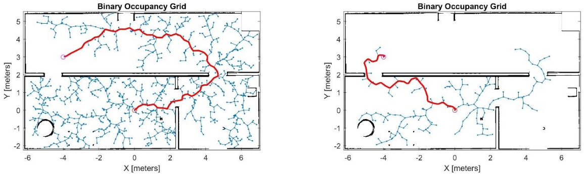
Examples of RRT and RRT Star search trees and planned paths in a binary occupancy grid
Example sampling-based planning results showing how different planners and random search processes can generate substantially different search trees and paths in the same environment.
Robot-Aware Planning

A collision-free point path is not enough

The occupancy map was expanded to account for the TurtleBot footprint. Obstacles were inflated before planning so that a nominally collision-free path would retain additional clearance during trajectory execution.

Robot kinematics were also represented through constrained state spaces rather than treating the robot as an unrestricted point moving in two dimensions.

Key constraints

  • Obstacle safety inflation: 0.18 m
  • Minimum turning radius: 0.143 m
  • Validation distance: 0.01 m
  • Deterministic random seed: 100
  • Maximum iterations: 10,000
  • Reeds-Shepp state space
  • Dubins state space
Planner Evaluation

Comparing path cost and search-tree size

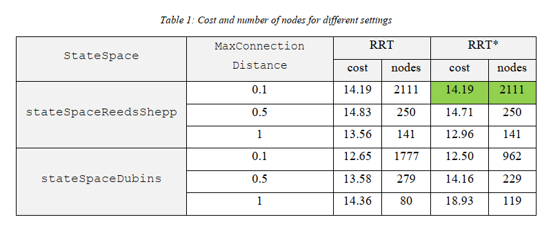
Planner behavior was compared by changing state space, connection distance, and planner type while preserving robot-specific constraints.

Table comparing RRT and RRT Star path cost and node count for Reeds-Shepp and Dubins state spaces
Cost and search-tree node count for multiple combinations of state space, maximum connection distance, RRT, and RRT*. The comparison demonstrates that planner performance is highly configuration-dependent.

Engineering observation

Increasing maximum connection distance generally reduced the number of search-tree nodes by allowing larger expansions. RRT* often produced lower-cost solutions, although planner randomness and route selection meant that it was not uniformly superior in every tested case.

Path Selection

The lowest numerical cost was not the only criterion

The final path was selected with execution safety in mind. A route passing through the center of the doorway was preferred because it provided greater clearance from surrounding obstacles.

This introduced an important engineering distinction: a mathematically shorter path is not necessarily the most robust path for a physical robot to execute.

Selection criteria

  • Valid collision-free path
  • Reasonable path cost
  • Manageable search-tree complexity
  • Doorway clearance
  • Robot turning constraints
  • Robustness during tracking
Trajectory Tracking

Planned path versus actual robot trajectory

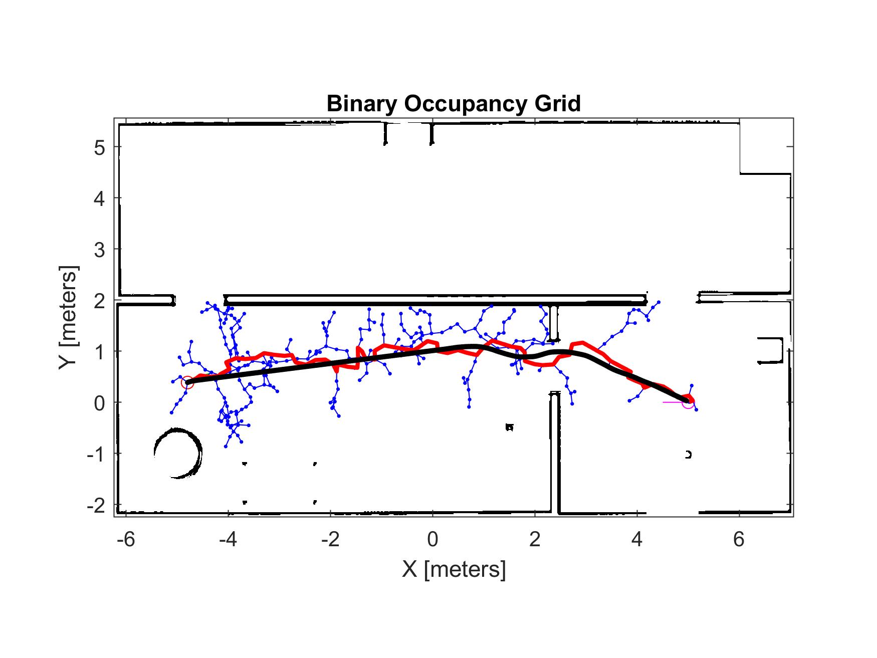
The planned waypoint path was executed using a Pure Pursuit controller and compared with the trajectory actually traveled by the TurtleBot.

RRT search tree with planned path and actual TurtleBot trajectory
Path-tracking result showing the sampling tree, planned path, and actual TurtleBot trajectory. The tracking trajectory does not exactly coincide with the geometric plan, highlighting the need for clearance during path design.
Additional Tracking Example

Different planning conditions produce different execution behavior

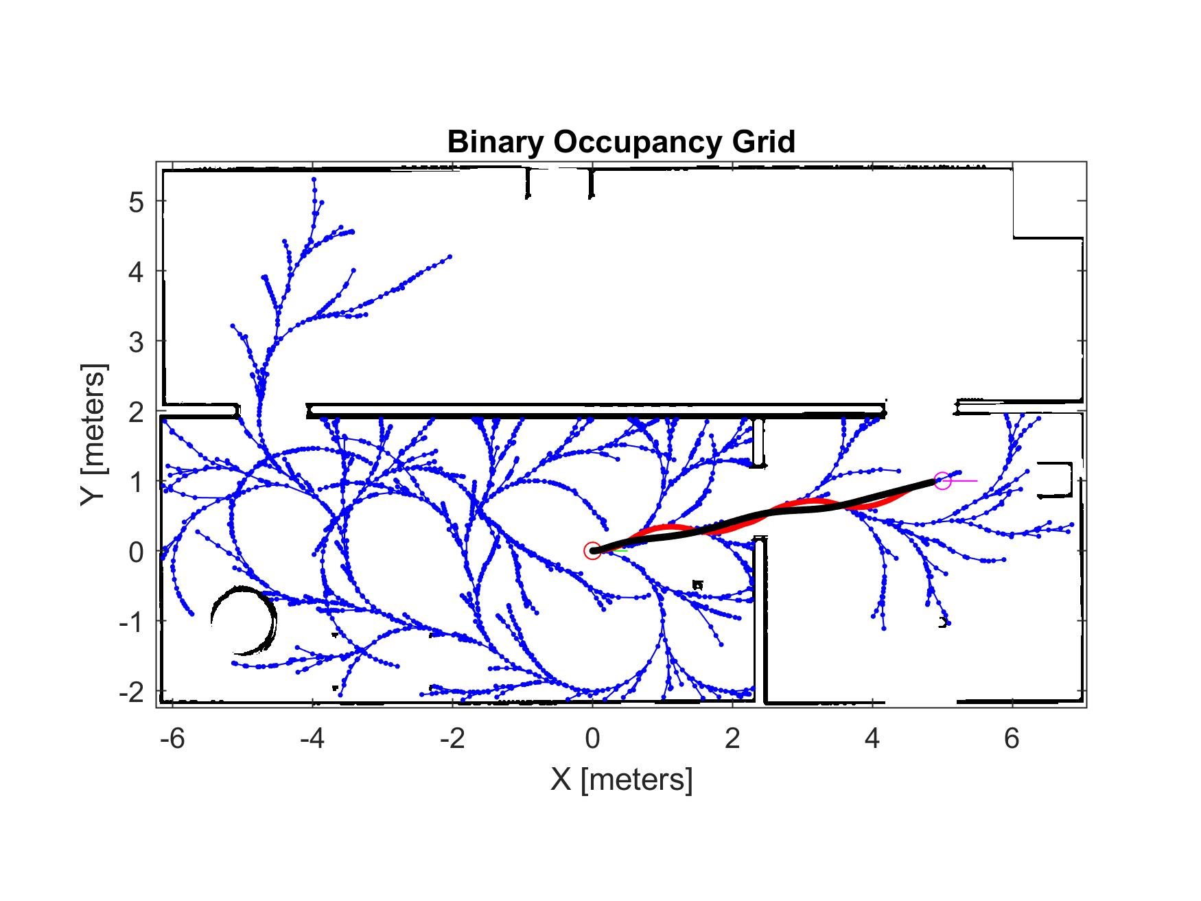
A second planning and tracking result reinforces the influence of randomized tree construction, path geometry, and controller behavior on the final robot motion.

Second RRT search-tree and TurtleBot trajectory tracking example
Additional planning and tracking example showing a different search tree and executed trajectory within the same occupancy-grid environment.
Engineering Limitations

Planning and execution are not identical problems

Even after inflating obstacles to account for robot size, collision remains possible if the tracking controller deviates from the planned path.

The lab therefore emphasized that path planning must include adequate safety clearance and should be evaluated together with the behavior of the downstream controller.

Practical limitations

  • Randomized planner output
  • Planner sensitivity to parameters
  • Finite collision-check resolution
  • Controller tracking error
  • Wall and corner clearance
  • Difference between geometric and executable paths
Teaching & Assessment

Students designed, tested, and defended their own planning choices

The laboratory gave students freedom to change planner configurations and design their own start and goal poses, encouraging experimentation rather than reproduction of a single fixed result.

Student reports were expected to explain planner behavior, discuss RRT limitations, interpret planning results, and identify methods for improving performance and robustness.

Assessment focus

  • RRT / RRT* theory
  • Planner implementation
  • Path design
  • Parameter selection
  • Path-following validation
  • Limitations and improvements
  • MATLAB code documentation
  • Technical reporting
My Role

Laboratory development, reference validation, and instruction

I developed and revised the laboratory material, validated the planning and trajectory-tracking workflow, prepared reference results and evaluation material, supported students during implementation and troubleshooting, and participated in grading and technical feedback.

The laboratory was designed to connect sampling-based planning theory with robot constraints, collision safety, planner configuration, and executable mobile-robot motion.

Responsibilities

  • Lab manual development
  • Reference-solution validation
  • Planner parameter testing
  • Gazebo / TurtleBot validation
  • Pure Pursuit tracking verification
  • Live laboratory instruction
  • Student troubleshooting
  • Grading and technical feedback
Laboratory Sequence

Completing the mobile-robotics laboratory sequence

The three main laboratories progressed from ROS and SLAM, through probabilistic localization, to path planning and trajectory execution.

LAB 01 ROS, SLAM & Navigation
→
LAB 02 AMCL Localization
→
LAB 03 RRT / RRT* Planning
← Back to Waterloo Research & Work