Control Systems · Part 1B
UR5e Controller Design, Benchmarking & Robustness
Building on the validated and characterized UR5e plant from Part 1A, I designed and evaluated PID, computed-torque, discrete LQR, and constrained MPC controllers on one common nonlinear benchmark. The study progresses beyond nominal tracking to diagnose controller-specific behavior, validate Python–C++ implementations, measure computation, and test robustness under persistent payload mismatch and a transient external disturbance.
1. Common Benchmark
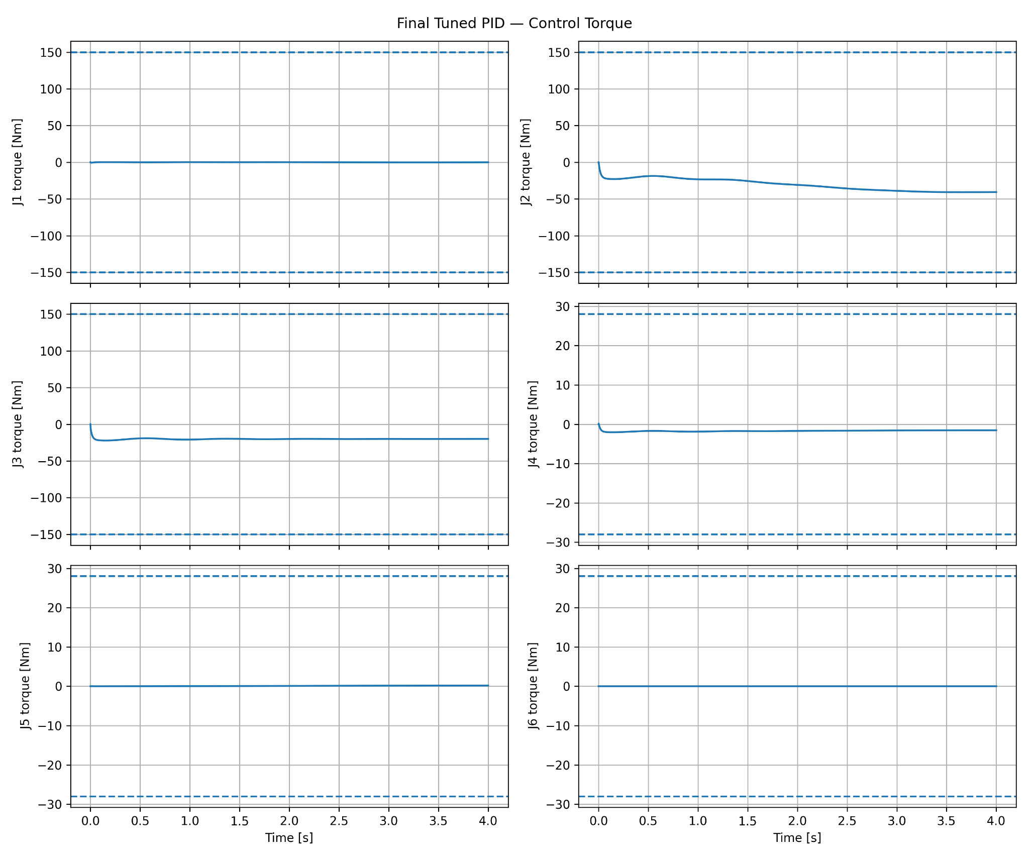
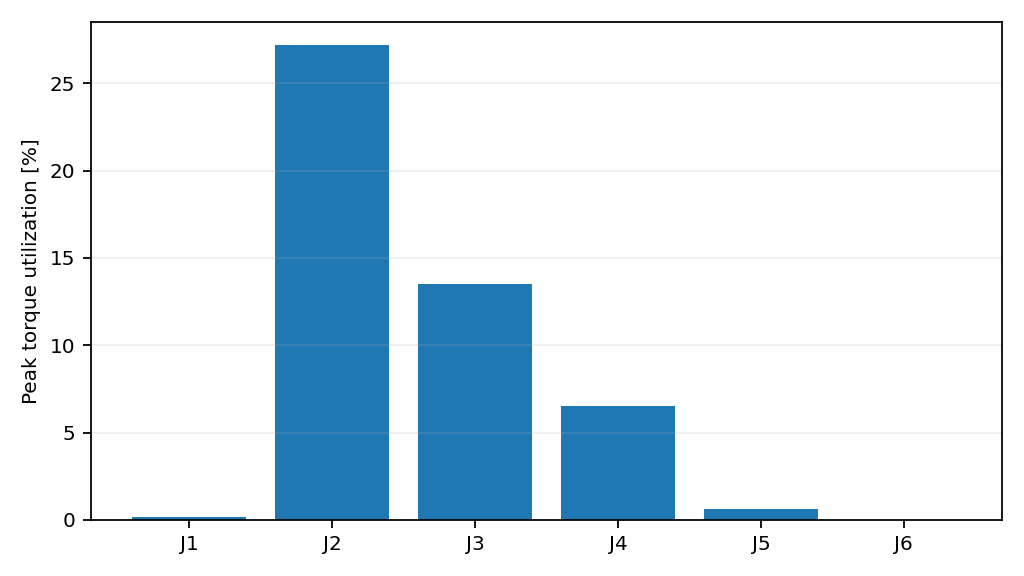
All controllers use the same validated nonlinear rigid-body plant, initial condition, reference trajectory, 2 ms sampling period, and modeled torque limits. The 4 s quintic trajectory moves from [0, -90, 90, -90, -90, 0]° to [20, -60, 60, -70, -70, 20]°. Part 1A established that this trajectory is dynamically meaningful without being saturation dominated.
| Controller | Joint RMSE | TCP Position RMSE | TCP Orientation RMSE |
|---|---|---|---|
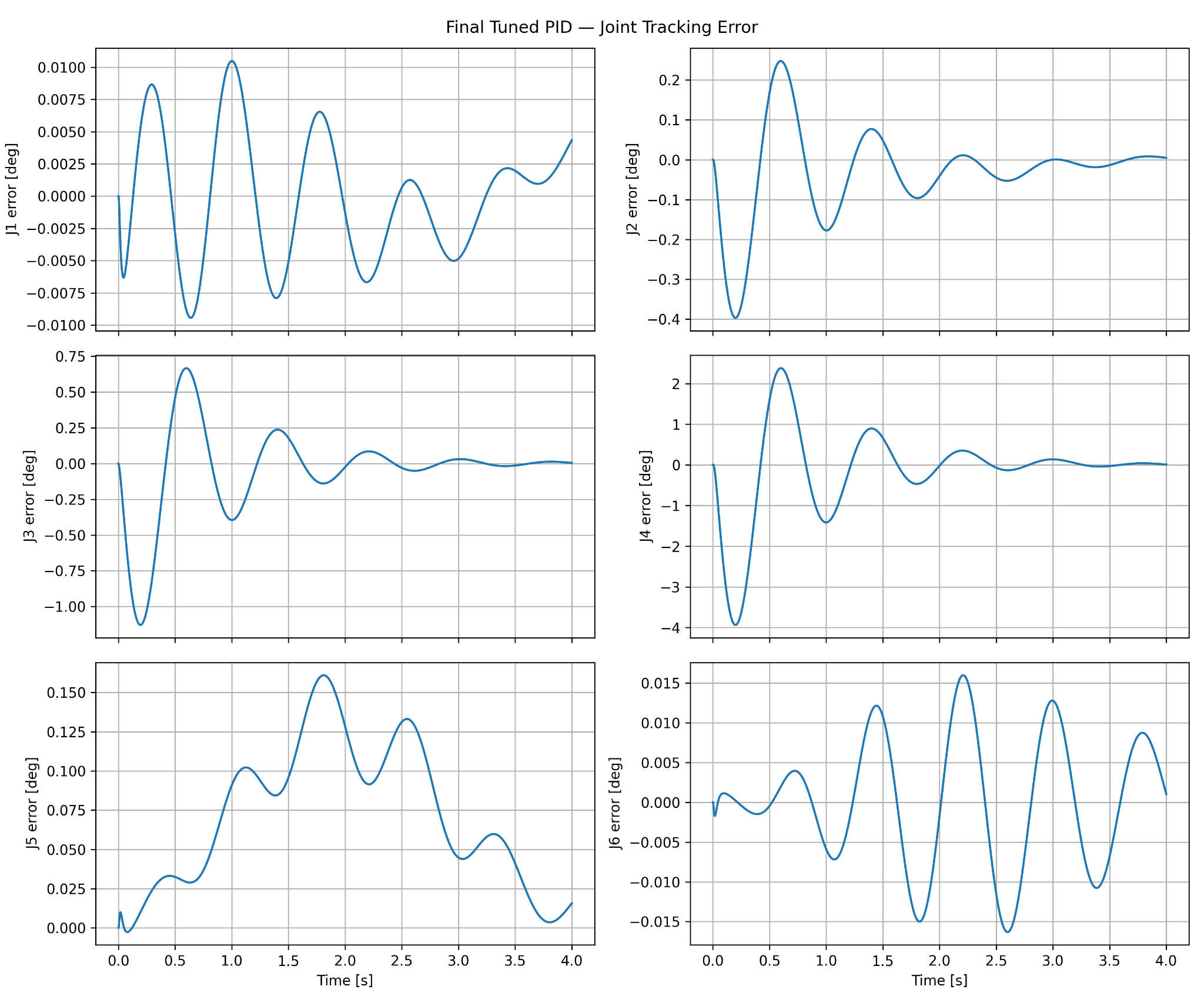
| PID | 0.469844° | 5.835795 mm | 1.527910° |
| Computed Torque | 0.001244° | 0.004139 mm | 0.002883° |
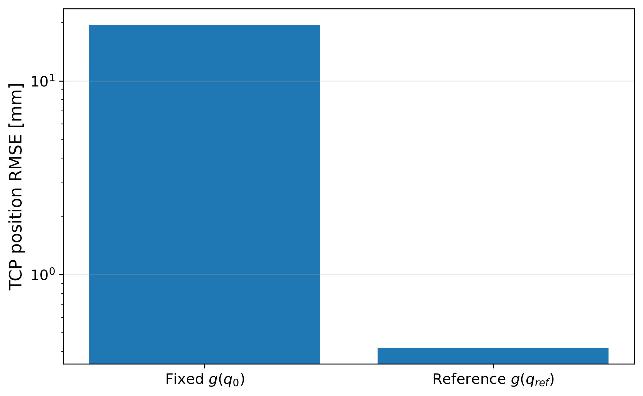
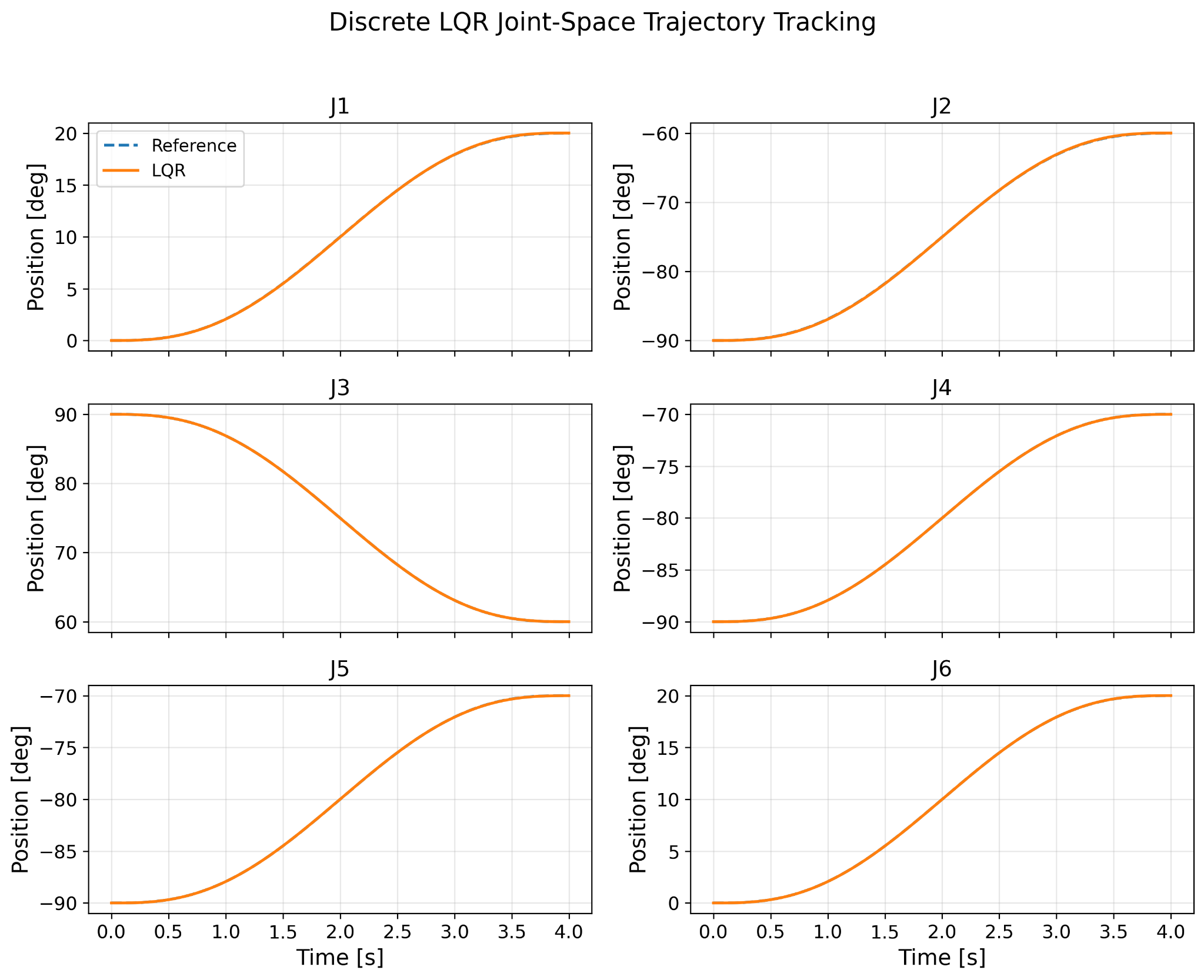
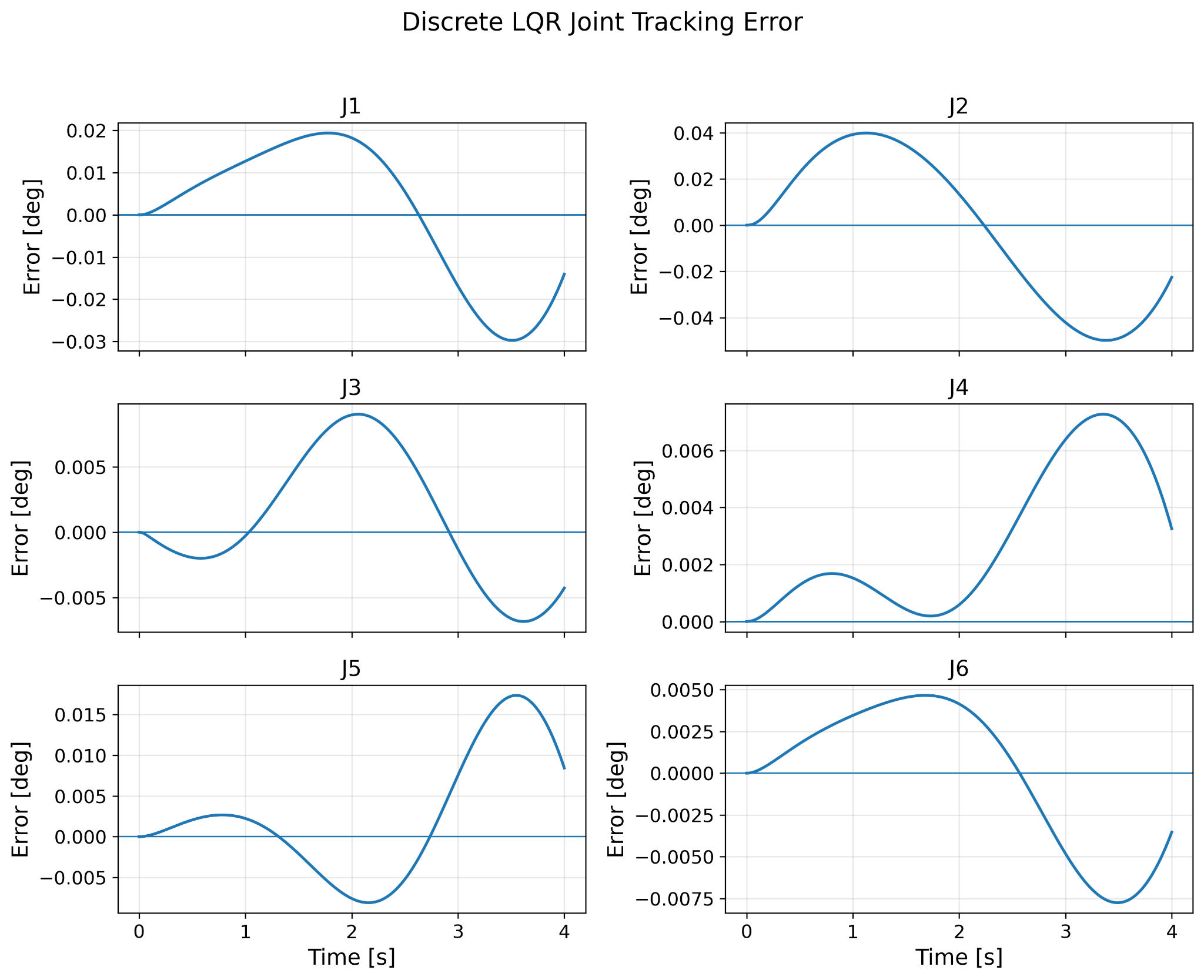
| LQR | 0.015502° | 0.418511 mm | 0.037763° |
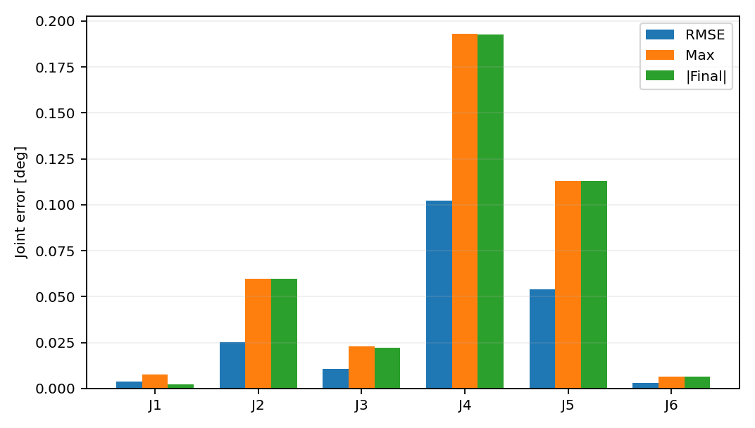
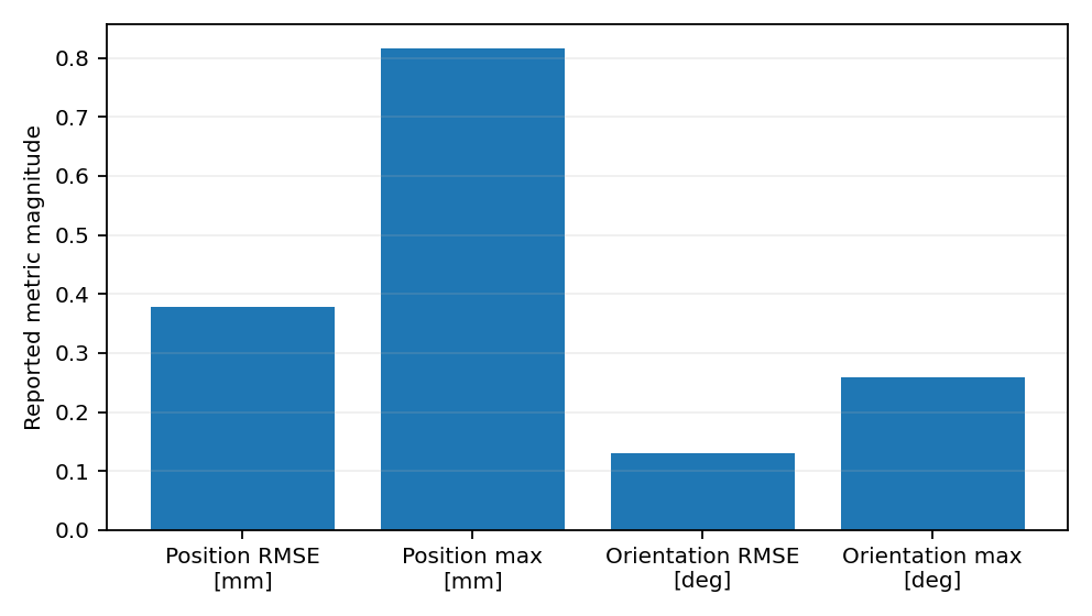
| MPC | 0.048474° | 0.378424 mm | 0.129772° |
2. PID — Feedback Baseline and Dynamic Diagnosis
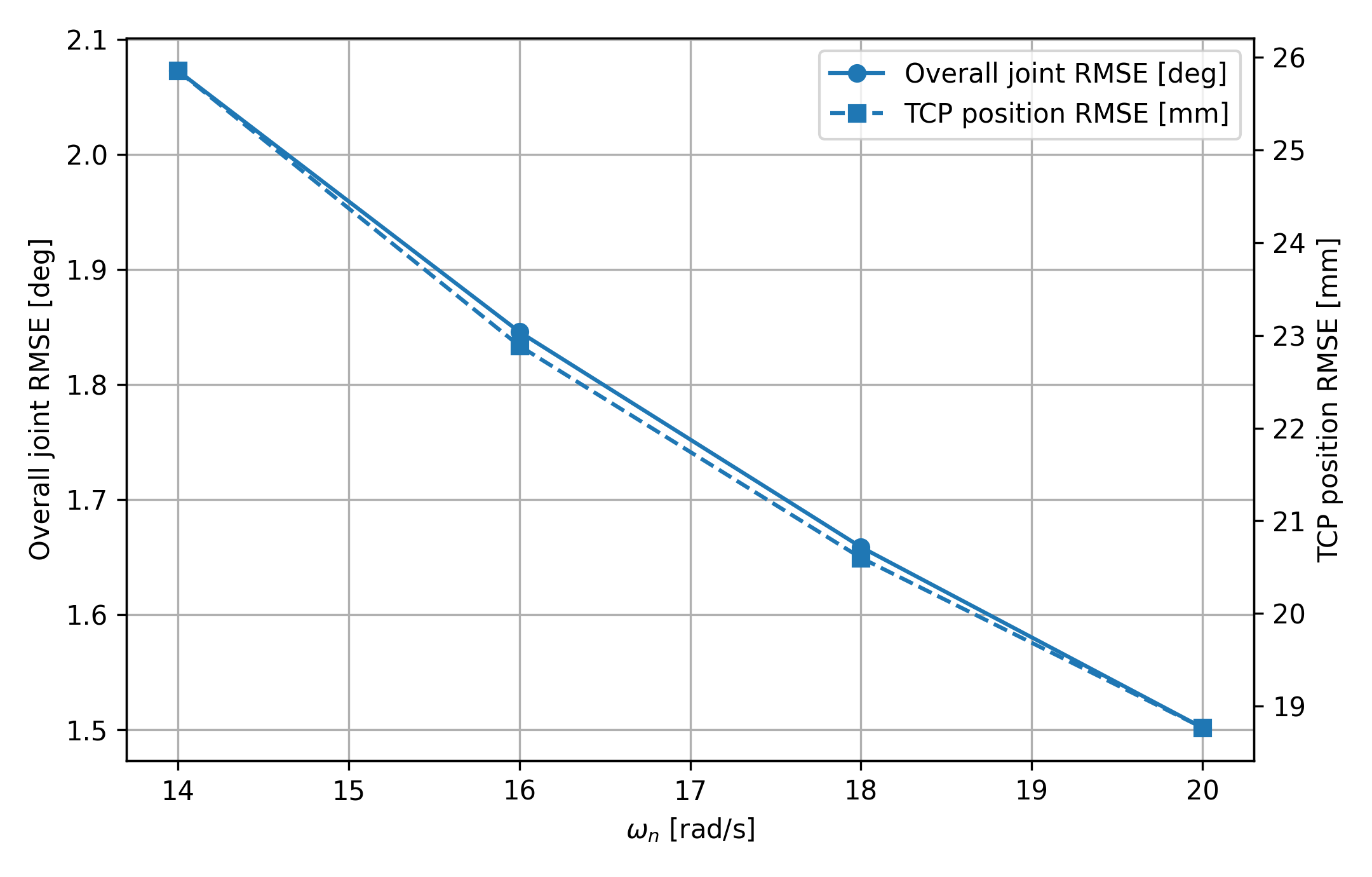
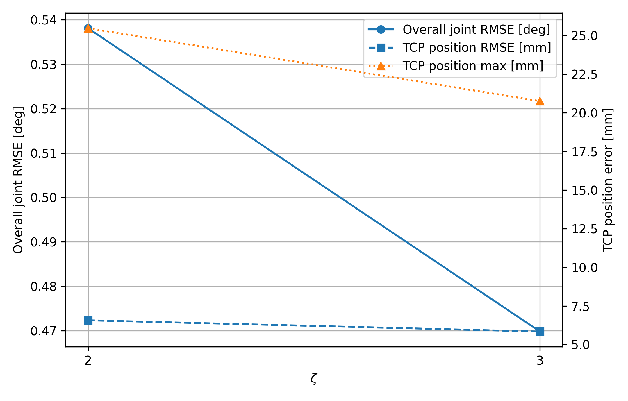
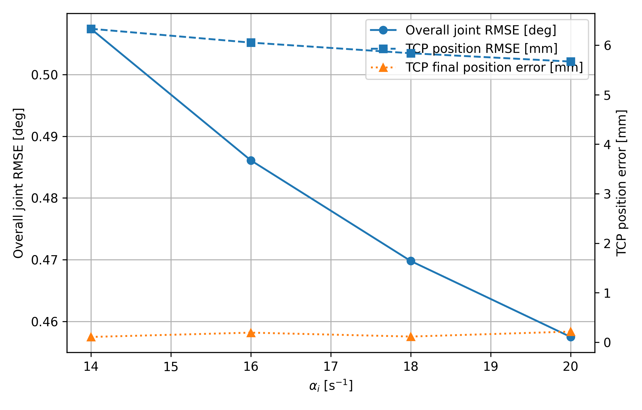
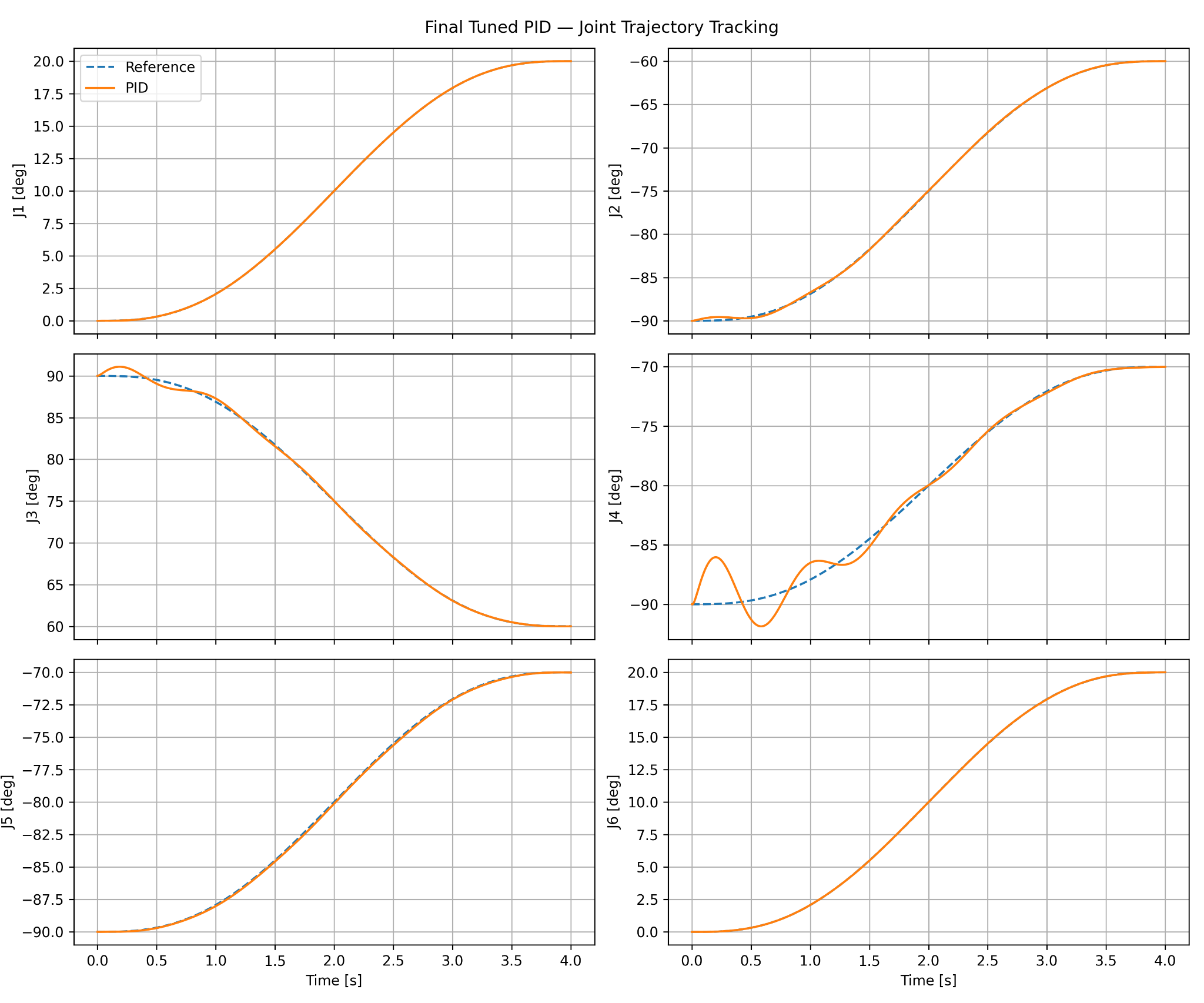
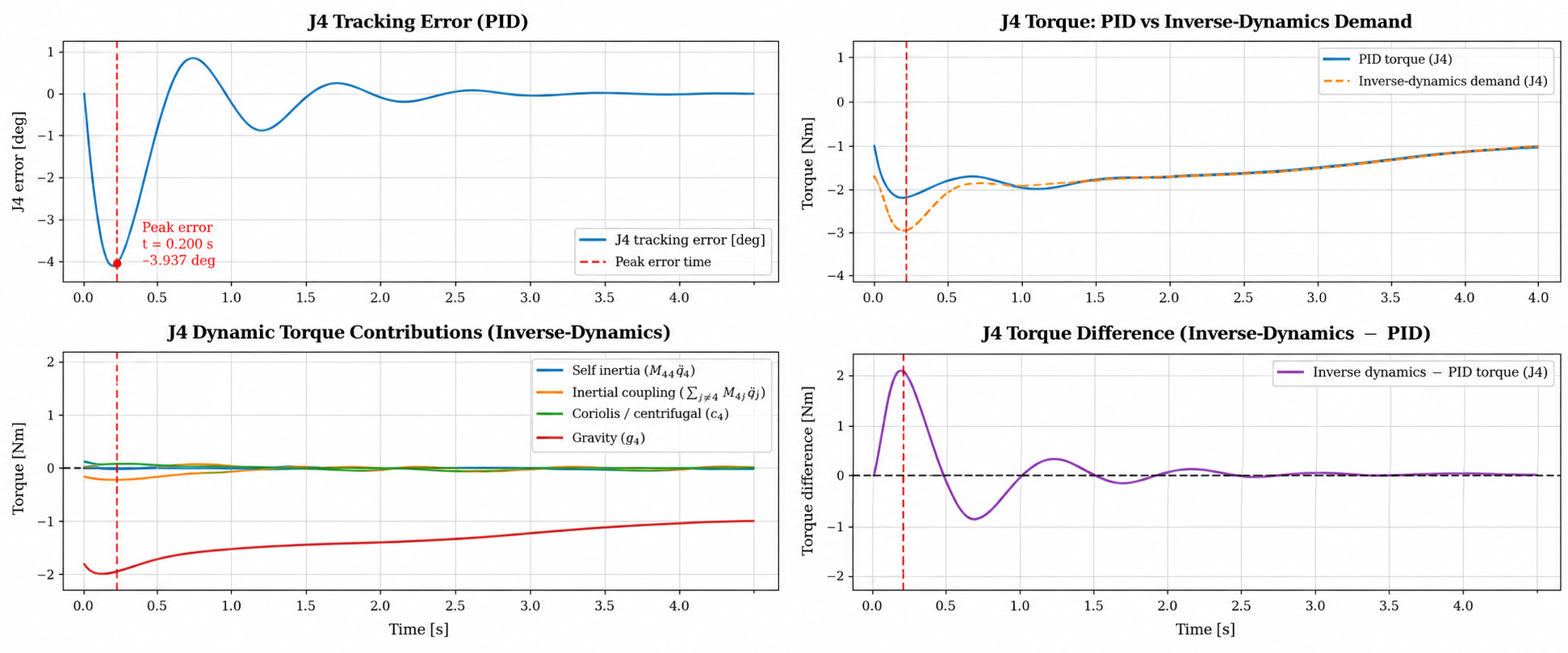
The joint-space PID was tuned through effective-inertia-based bandwidth, damping, and integral-gain studies. The final design uses ωn = 20 rad/s, ζ = 3, and αi = 18. Instead of treating the remaining J4 error as a generic gain problem, I decomposed the dynamics and found that the behavior was primarily gravity dominated rather than saturation or coupling dominated.
3. Computed Torque — Nominal Accuracy and Model Dependence
Computed-torque control uses the nominal rigid-body model to cancel the modeled dynamics and impose second-order error behavior. With the controller model and plant exactly matched, it achieved 0.001244° overall joint RMSE and 0.004139 mm TCP position RMSE.
The commanded torque closely reproduces the Part 1A inverse-dynamics benchmark. I therefore treated the exceptional nominal result as a reason to test model sensitivity rather than as proof of universal superiority. The 2 kg payload case later exposes that dependence directly.
4. Discrete LQR — Diagnosing the Feedforward Structure
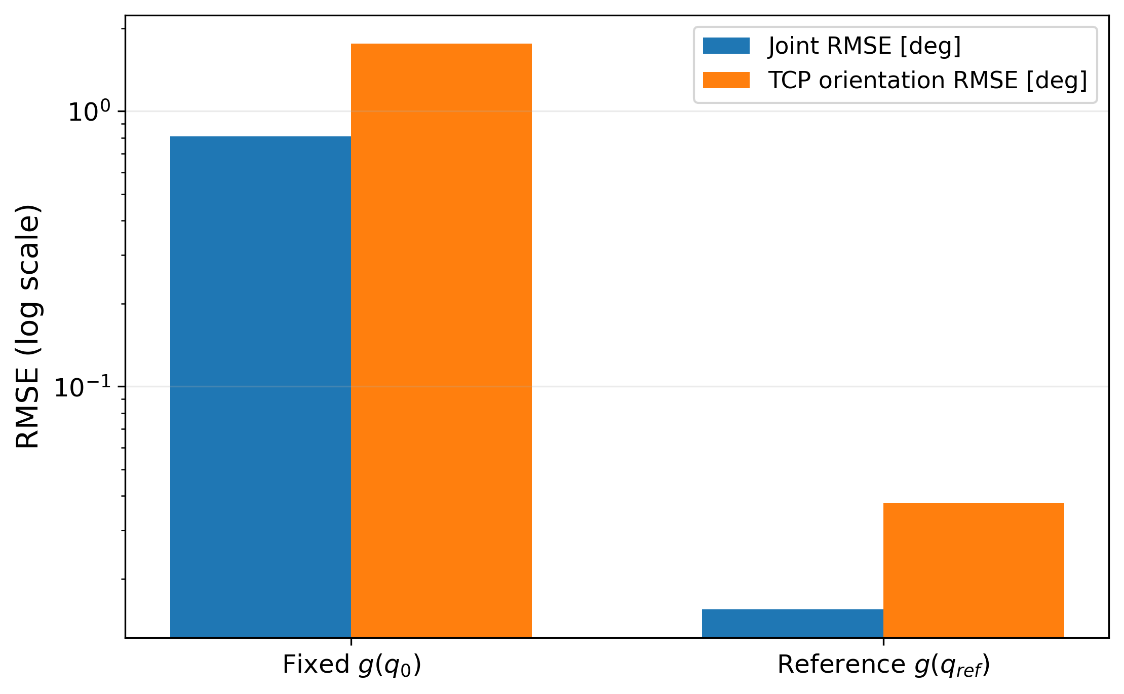
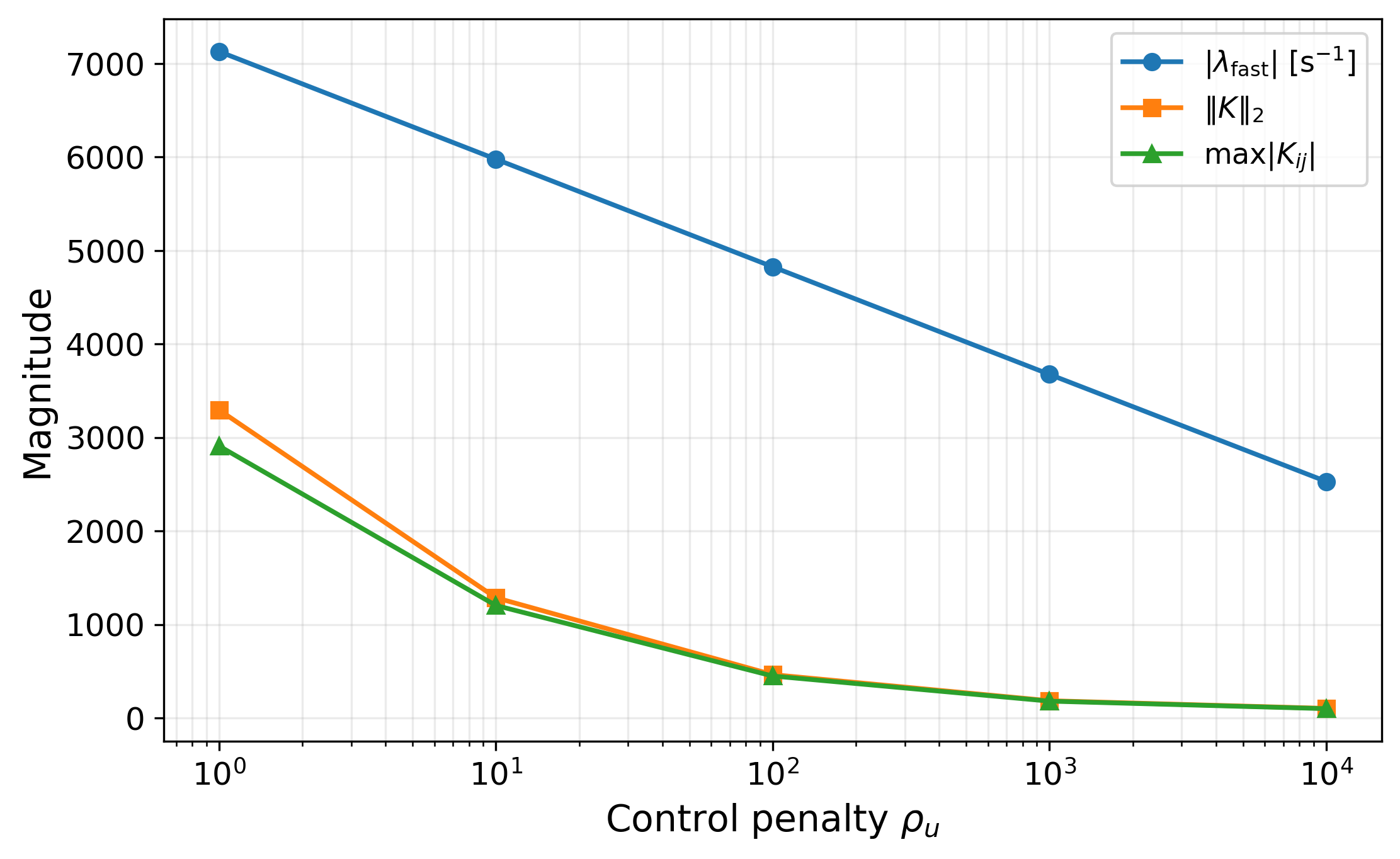
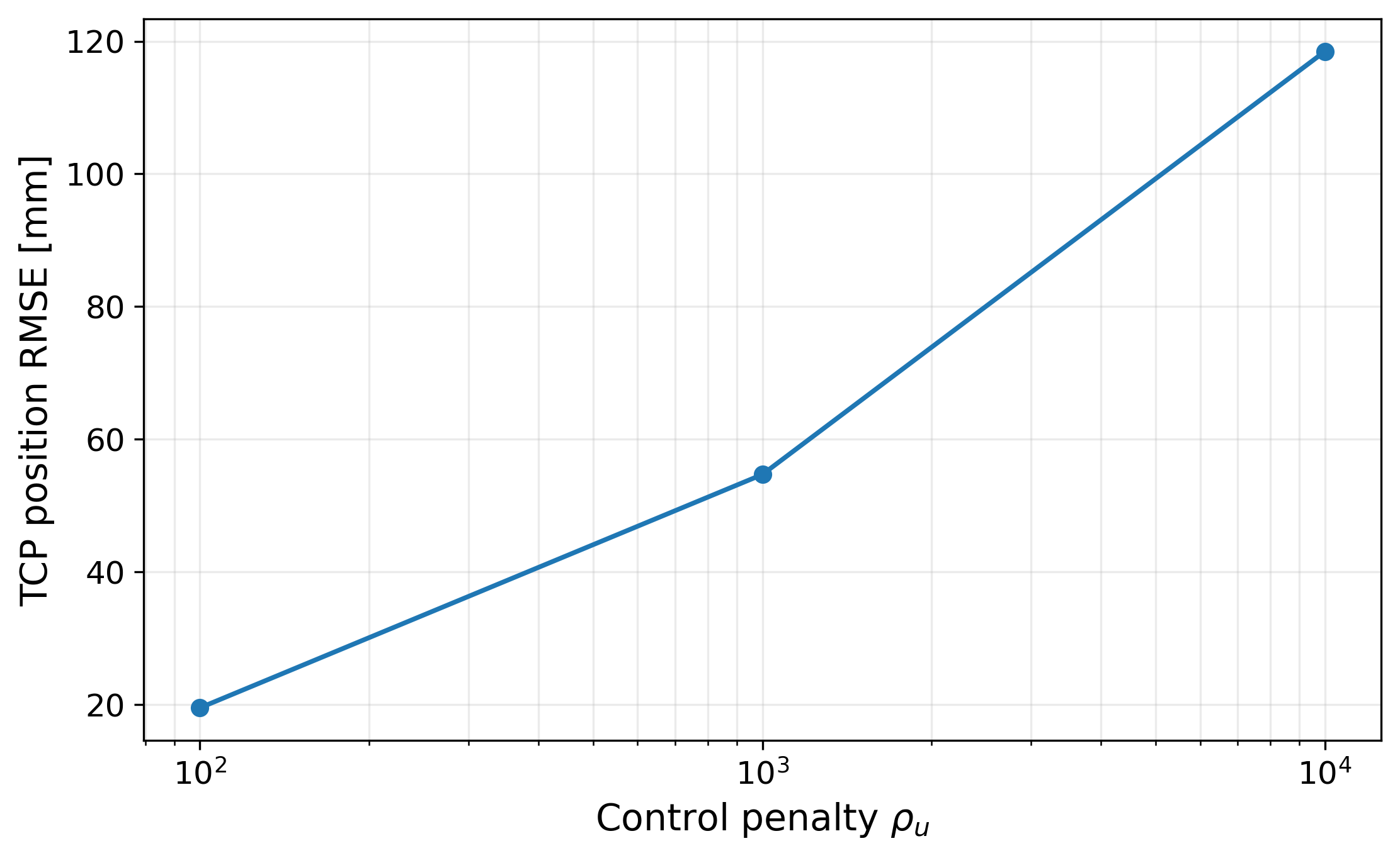
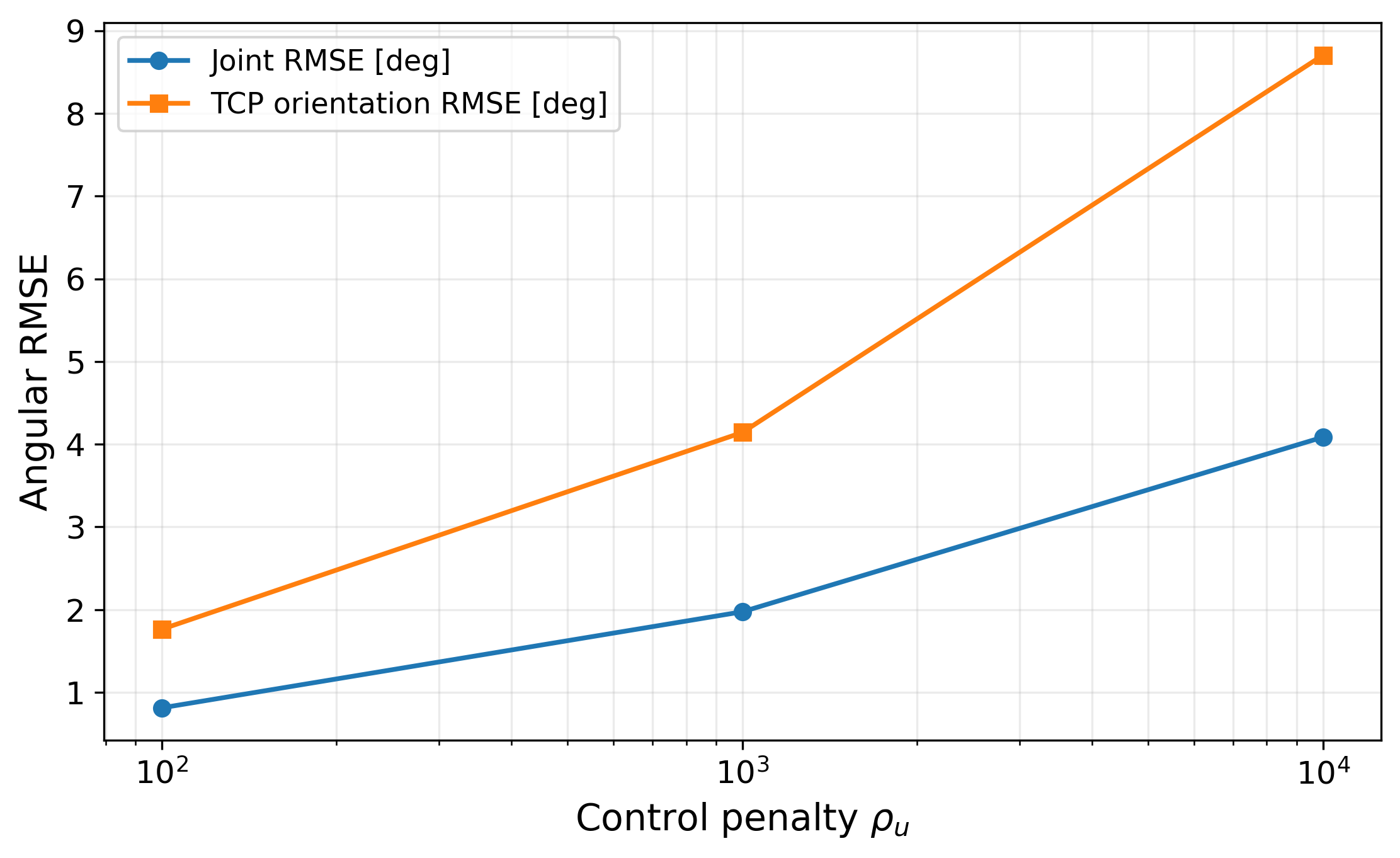
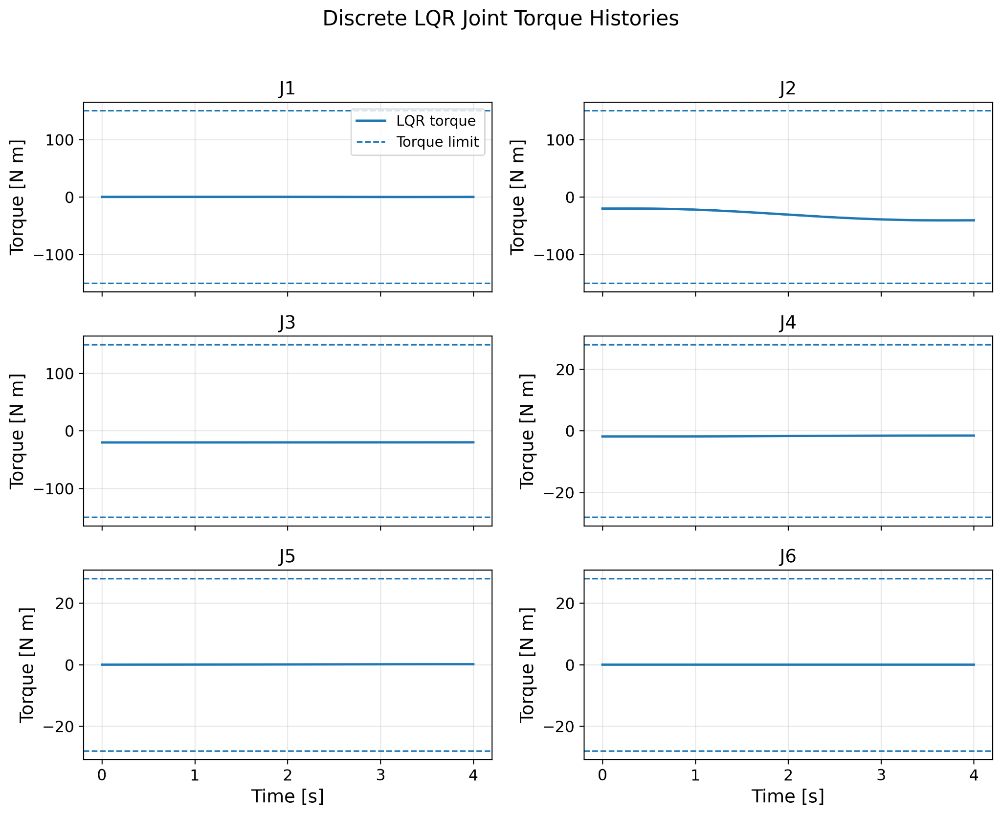
The first local LQR implementation performed poorly on the nonlinear trajectory. The result was retained as a diagnostic step. A fixed equilibrium gravity term did not follow the changing reference configuration. The final design uses exact ZOH discretization, a DARE solution, Bryson-style normalization, ρu = 100, and reference-dependent gravity feedforward.
5. Constrained MPC — Prediction and Runtime Architecture
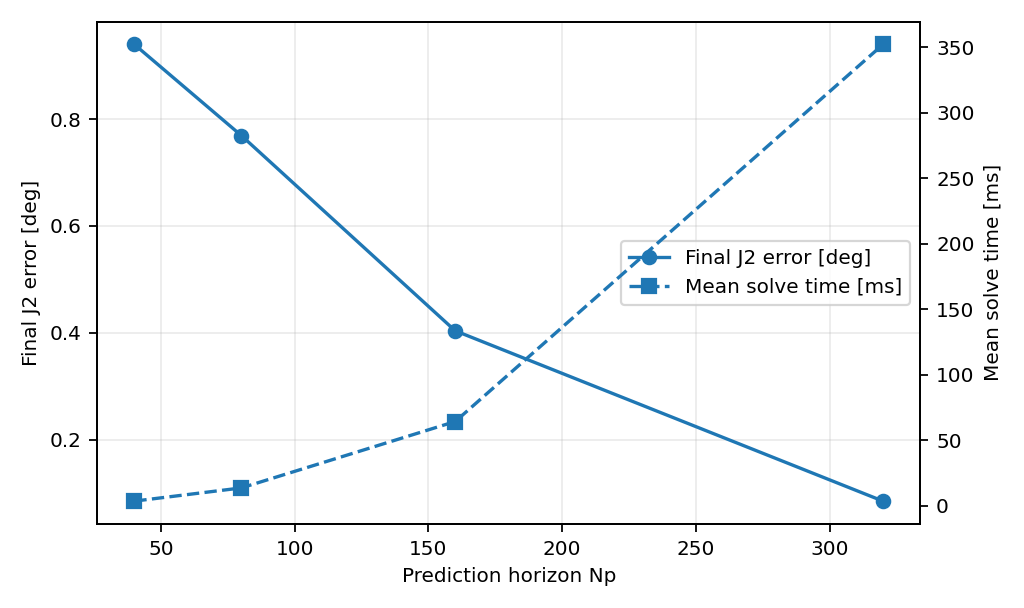
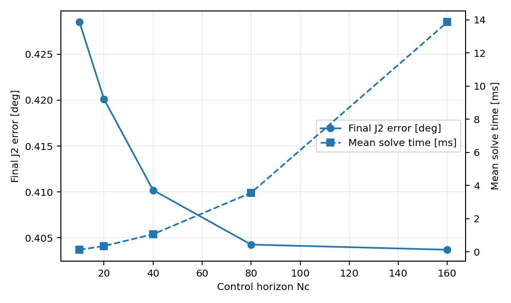
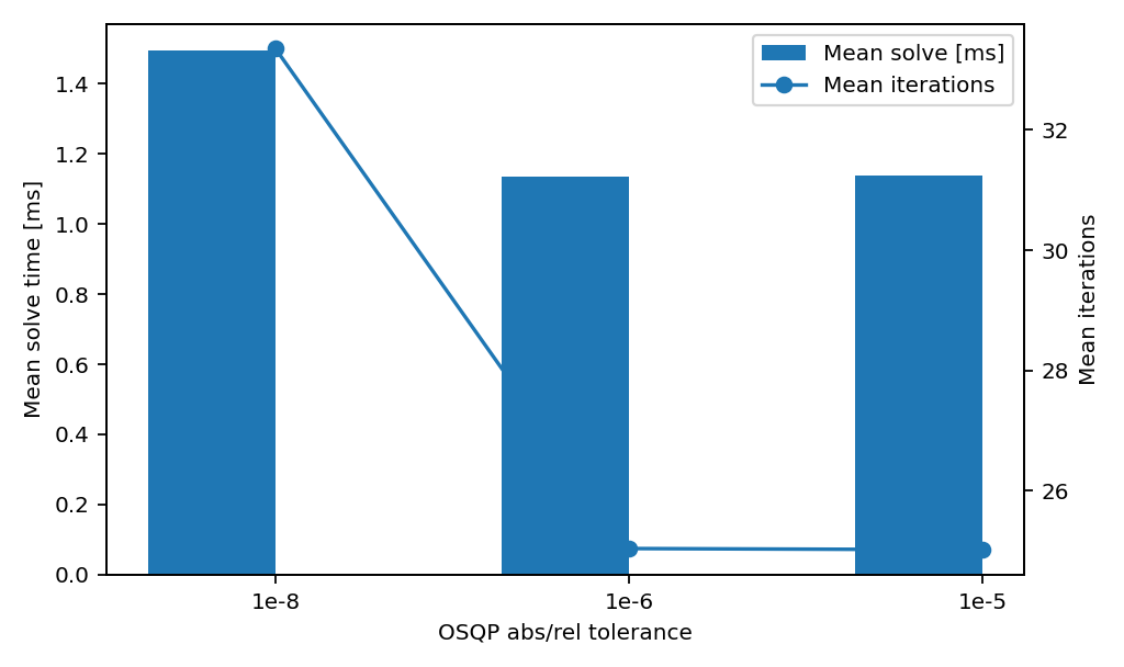
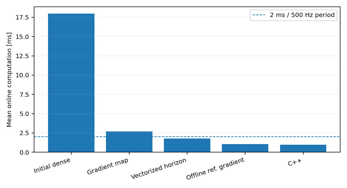
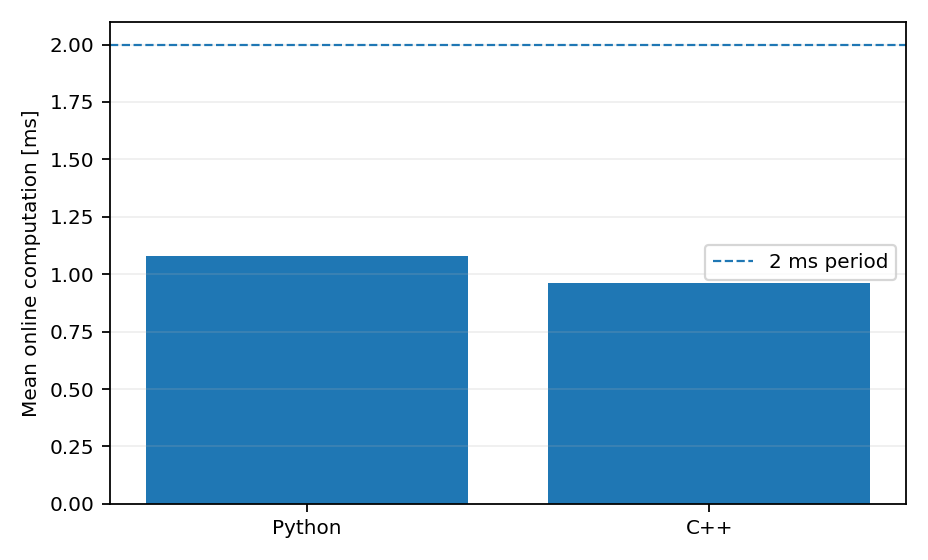
The final linear MPC uses Np = 160 (320 ms), Nc = 40 (80 ms), ρu = 10, and explicit joint-torque constraints in an OSQP quadratic program. Profiling showed that known reference-dependent QP terms were being rebuilt online. I separated the gradient into state-dependent and known reference-dependent components and moved the latter offline, preserving the controller mathematics while reducing online computation.
6. Robustness Methodology
Nominal accuracy and robustness were intentionally separated. Final controller parameters were frozen and two different perturbation mechanisms were applied to the actual plant.
R1 — Persistent Model Mismatch
A 2.0 kg point payload is placed 0.10 m along tool-frame +Z. The actual plant changes inertia and gravity while every controller continues to use its nominal bare-arm design model.
R2 — External Disturbance
A +20 Nm generalized torque is applied to Joint 2 for 200 ms from t = 2.0 s. The nominal plant itself is unchanged and the controller is not informed of the disturbance.
7. Robustness Results
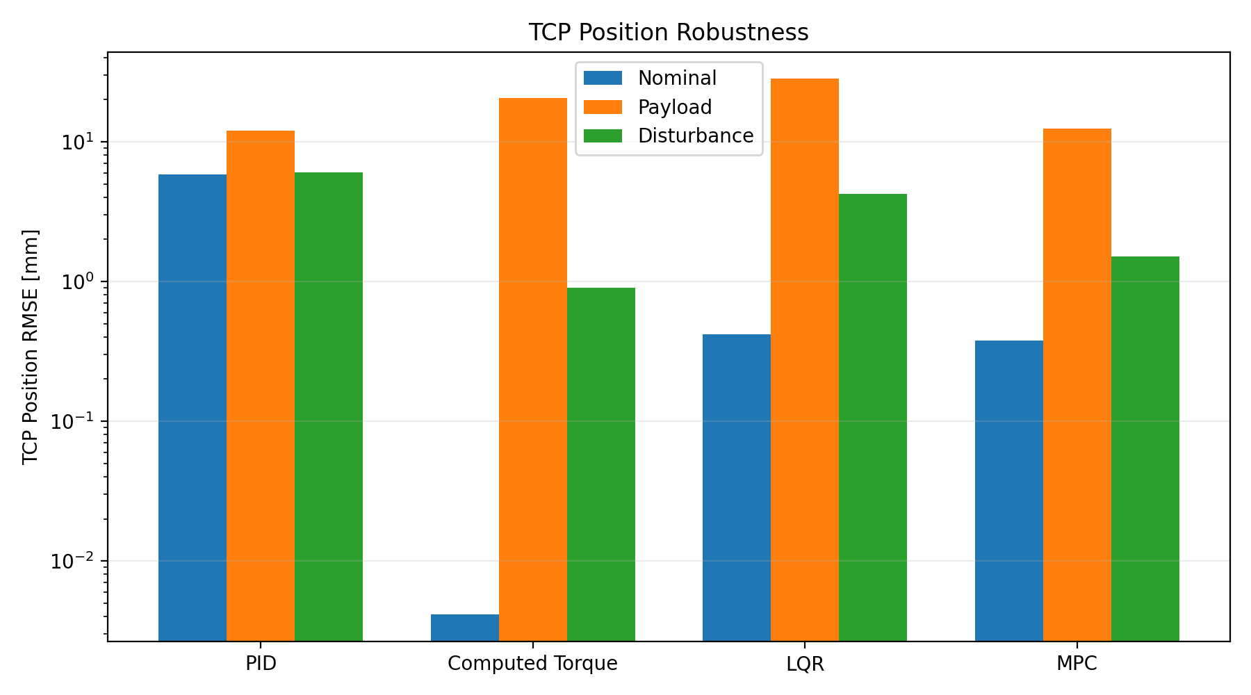
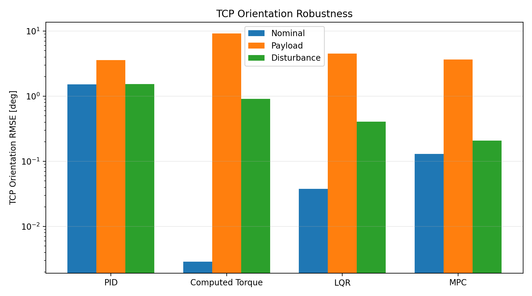
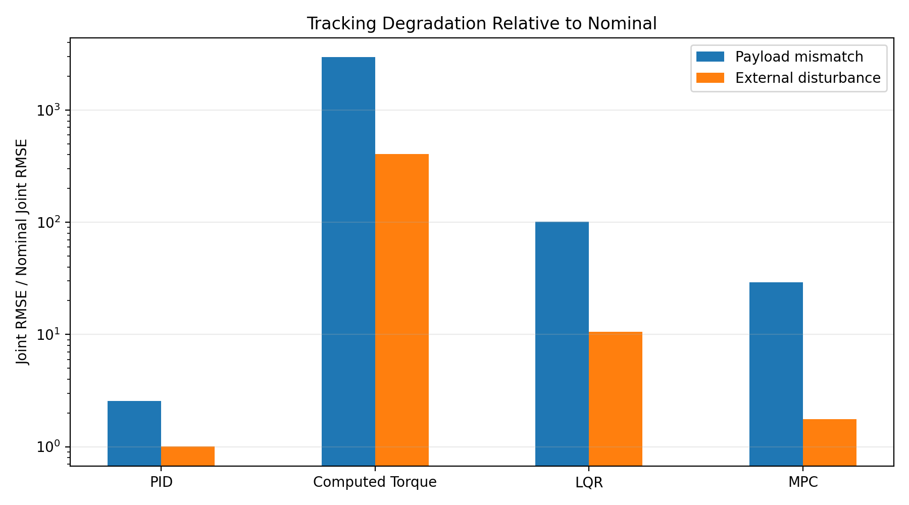
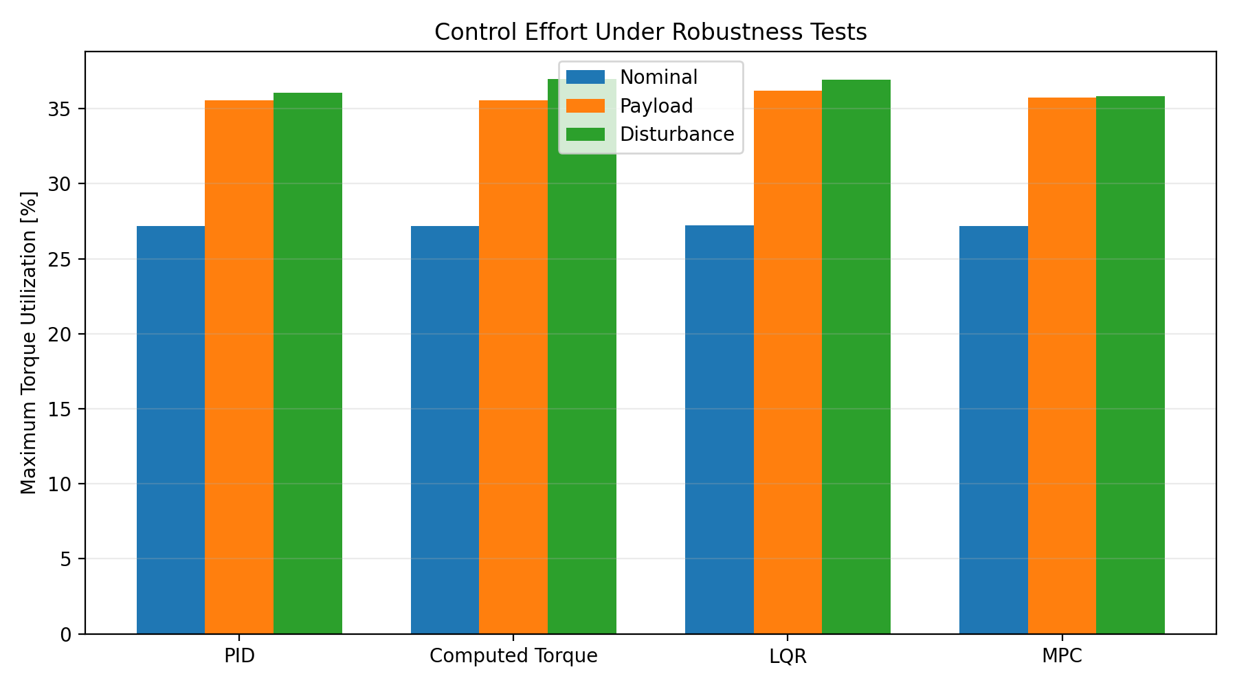
| Controller | Case | Joint RMSE [deg] | TCP Position [mm] | TCP Orientation [deg] |
|---|---|---|---|---|
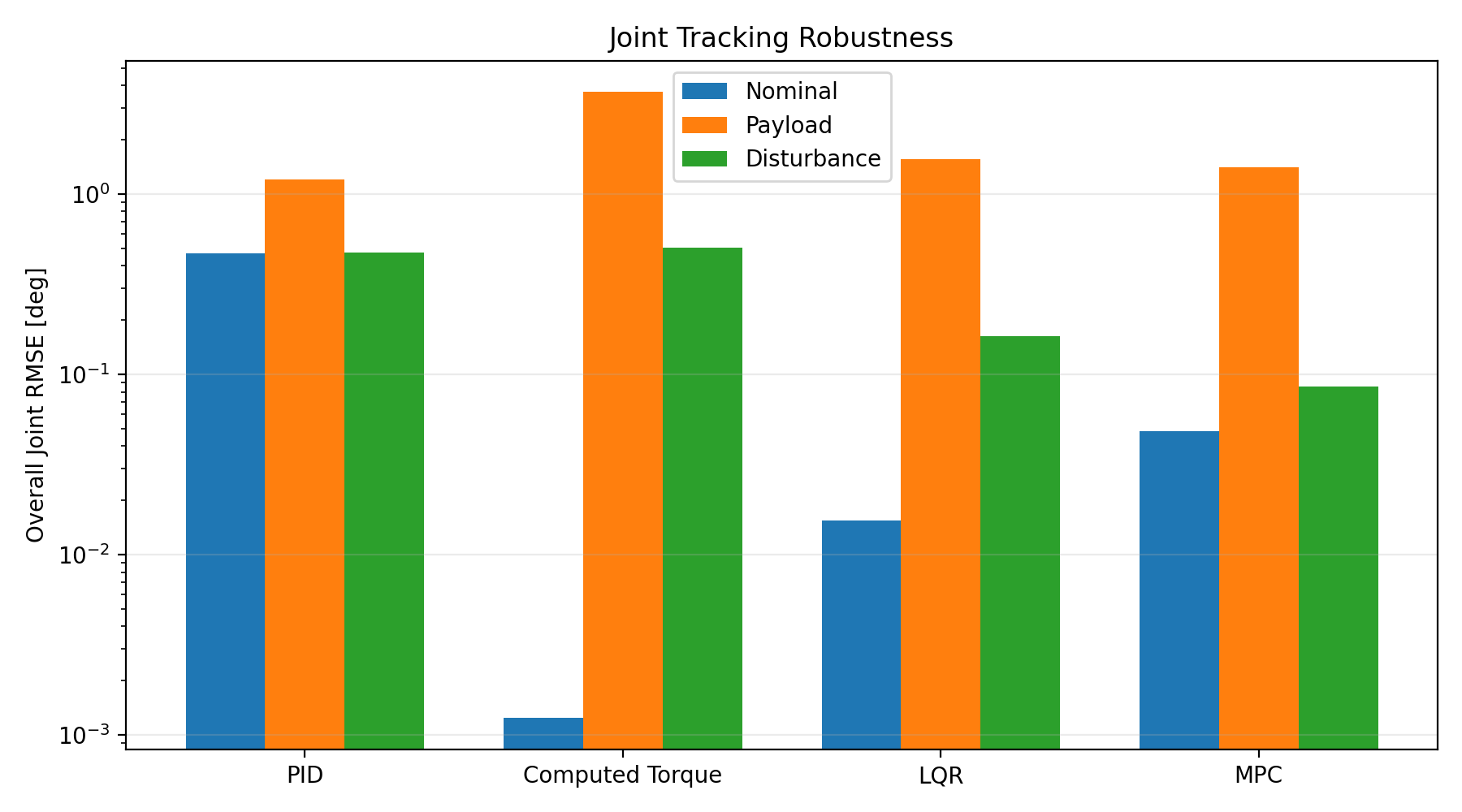
| PID | Nominal | 0.469844 | 5.835795 | 1.527910 |
| PID | Payload | 1.205309 | 11.963438 | 3.585649 |
| PID | Disturbance | 0.472416 | 6.032206 | 1.531076 |
| Computed Torque | Nominal | 0.001244 | 0.004139 | 0.002883 |
| Computed Torque | Payload | 3.684475 | 20.562134 | 9.174375 |
| Computed Torque | Disturbance | 0.504513 | 0.900220 | 0.907051 |
| LQR | Nominal | 0.015502 | 0.418511 | 0.037763 |
| LQR | Payload | 1.564289 | 28.293832 | 4.533704 |
| LQR | Disturbance | 0.163066 | 4.246570 | 0.406142 |
| MPC | Nominal | 0.048474 | 0.378424 | 0.129772 |
| MPC | Payload | 1.412378 | 12.380191 | 3.659589 |
| MPC | Disturbance | 0.085670 | 1.503611 | 0.209132 |
8. Engineering Conclusions
Nominal Precision ≠ Robustness
Computed torque is exceptionally accurate under exact model match, while persistent payload mismatch exposes the sensitivity of model cancellation. The two tests measure different properties.
Transient ≠ Persistent Uncertainty
The J2 pulse disappears after 200 ms while the payload mismatch persists. Separating the cases prevents disturbance rejection and model robustness from being treated as the same engineering problem.
Constraints Were Not the Story Here
MPC includes explicit torque constraints, but none of the current tests activates them. The present results therefore support conclusions about tracking, computation, and robustness—not a demonstrated constraint-handling advantage.
Implementation Matters
PID exposed update-order details, LQR exposed feedforward structure, and MPC exposed the distinction between controller mathematics and online software architecture. Python–C++ cross-validation ensured implementation changes preserved the intended controller.
9. Technical Reports
Integrated Part 1B Report
Full controller-design, nominal-benchmark, computation, Python–C++ validation, and robustness assessment.
PID Controller Report
Detailed tuning, final benchmark, J4 dynamic diagnosis, and implementation analysis.
LQR Controller Report
Discrete design, gravity-feedforward diagnosis, nonlinear tuning, and Python–C++ validation.
MPC Controller Report
QP formulation, horizon/tolerance studies, computation profiling, offline/online restructuring, and C++ runtime validation.
Project by Sooyong Kim · Robotics Control Portfolio