Robotics Portfolio Project 03
LiDAR-Camera 3D Perception & Fusion
A ROS 2 multi-modal perception pipeline that combines open-vocabulary RGB detection, prompted instance masks, calibrated LiDAR-to-camera projection, depth-based association, and robust 3D statistics in a warehouse simulation environment.
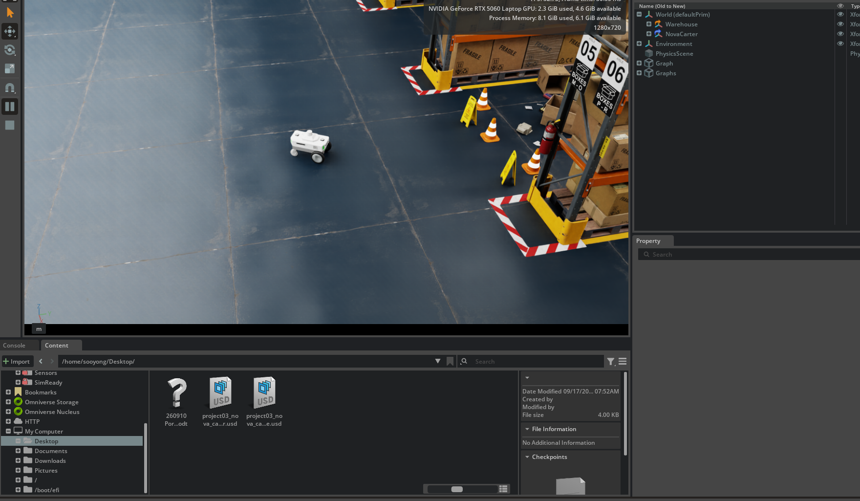
Demo
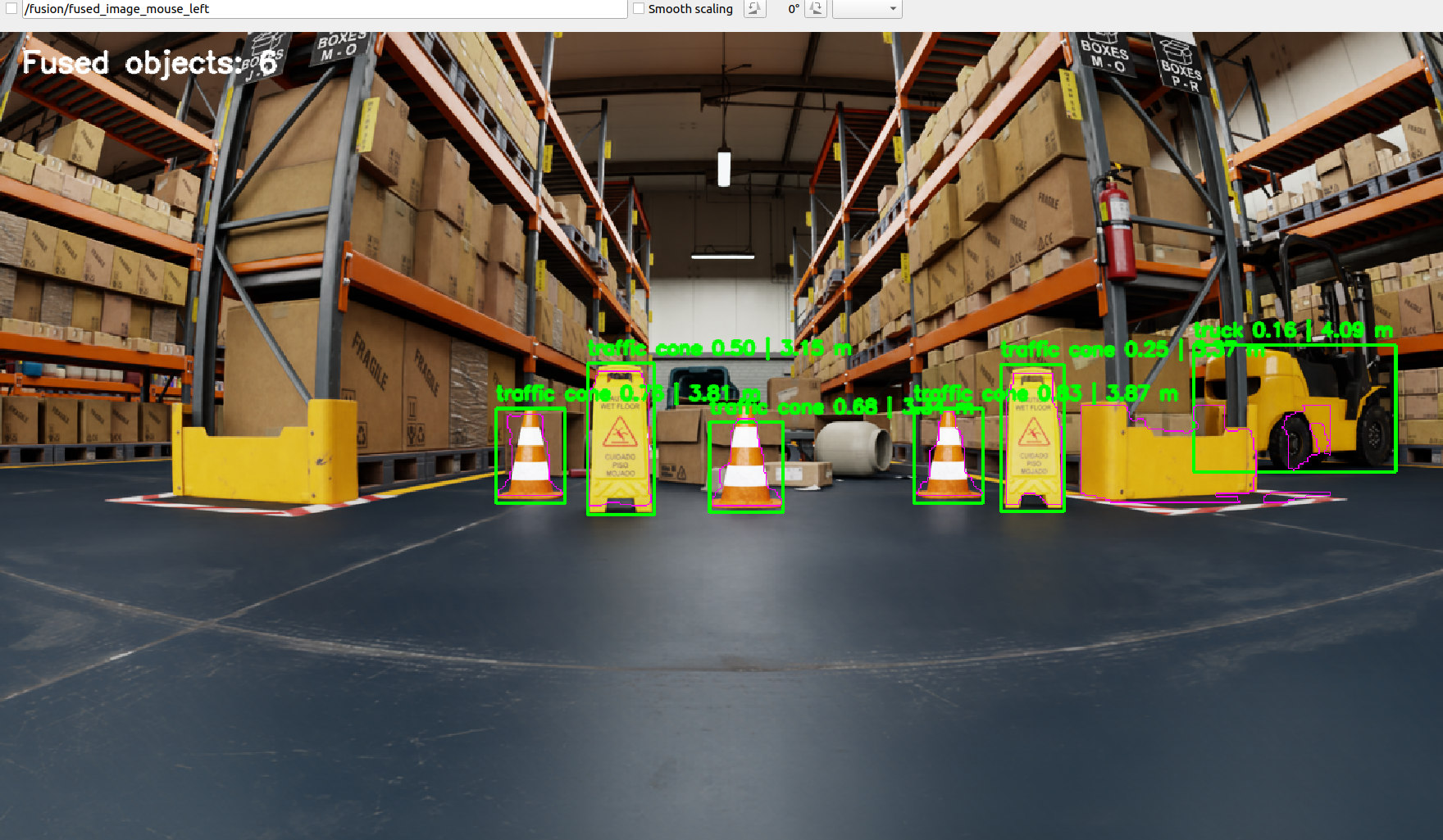
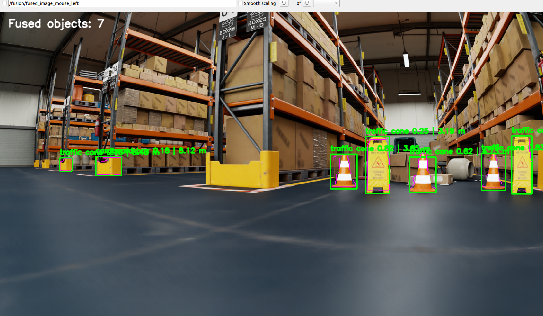
The demo is intended as a qualitative visualization of detection, mask generation, LiDAR association, and object-level distance estimation. Quantitative conclusions are based on the controlled experiments summarized below.
1. Project Objective
RGB cameras provide dense semantic information but do not directly measure metric depth. LiDAR provides accurate 3D geometry but lacks rich semantic interpretation. The purpose of this project was to combine these complementary sensing modalities into a practical ROS 2 perception pipeline that can associate camera detections with geometrically consistent LiDAR returns.
The project focuses on three engineering questions: whether LiDAR points can be projected reliably into the image plane using calibrated sensor geometry, whether object-level depth can be estimated robustly from the projected points, and how the fusion pipeline behaves when viewpoint, sensing range, and extrinsic calibration are deliberately changed.
2. Processing Architecture
The RGB and LiDAR streams remain separate until geometric projection creates a common image-plane reference. The camera branch provides semantic object hypotheses, while the LiDAR branch provides metric 3D measurements. The two streams are associated using either a detector bounding box or a prompted segmentation mask before robust depth statistics are computed.

3. Coordinate Transformation and Projection
A LiDAR return is initially expressed in the LiDAR coordinate frame and must be
transformed into the camera frame before it can be compared with image detections.
For a LiDAR point pL, the camera-frame point is obtained through
the rigid-body extrinsic transform
pC = RCL pL + tCL.
Only points with positive camera-frame depth are retained.
The transformed 3D points are then projected with the camera intrinsic parameters:
u = fxX/Z + cx and
v = fyY/Z + cy.
This geometric step creates the bridge between a 3D LiDAR measurement and a 2D
camera detection. Errors in the extrinsic transform therefore shift projected
LiDAR points relative to the visual object, which motivates the calibration-sensitivity
experiment later in the project.
4. Viewpoint and Range Robustness
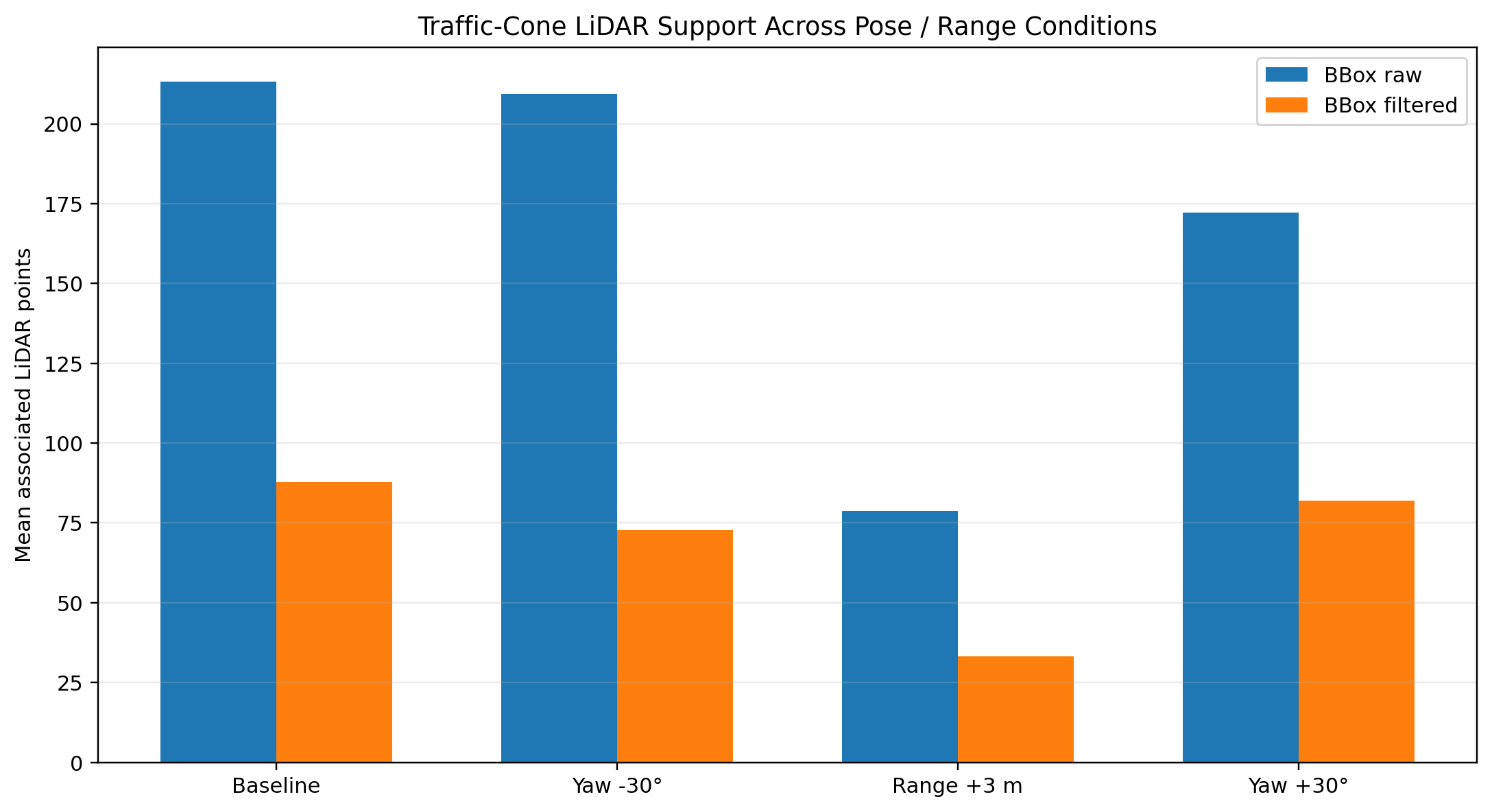
The robot pose was changed in a controlled manner while the fusion algorithm and sensor calibration remained fixed. This isolates the effect of viewpoint and target range without mixing it with changes to the fusion algorithm itself. The baseline pose was compared with a 30° left-view condition, a 3 m increased-range condition, and a 30° right-view condition.
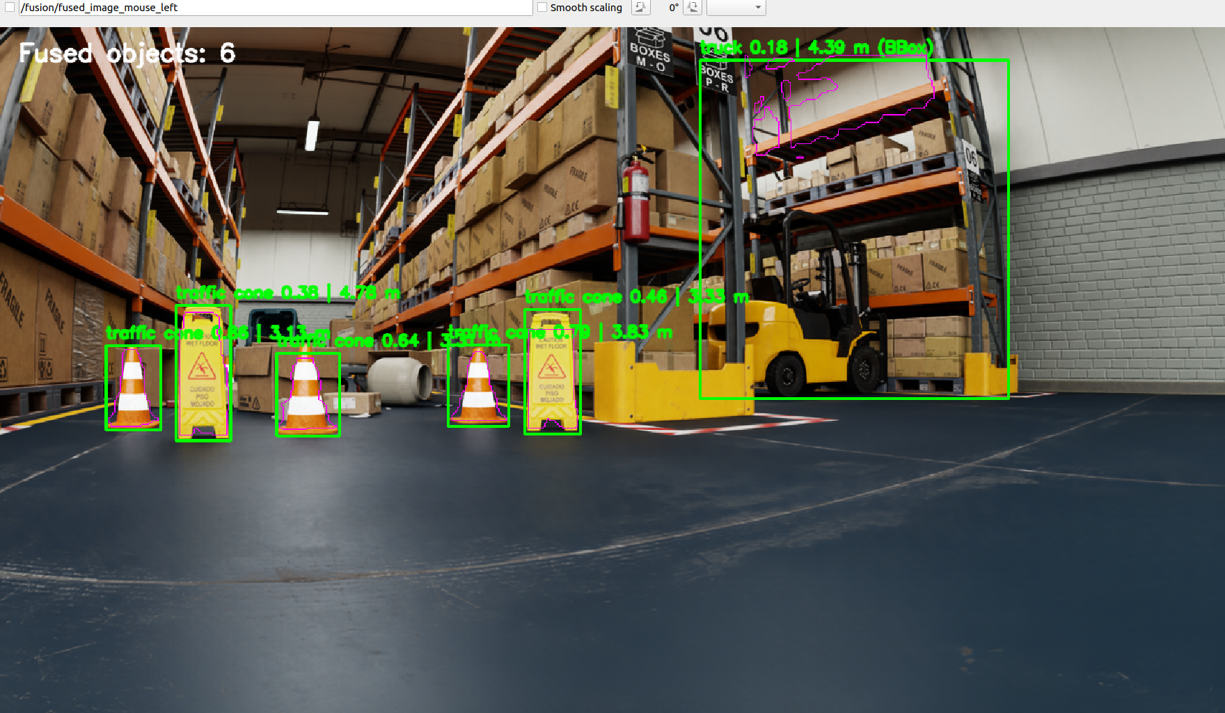
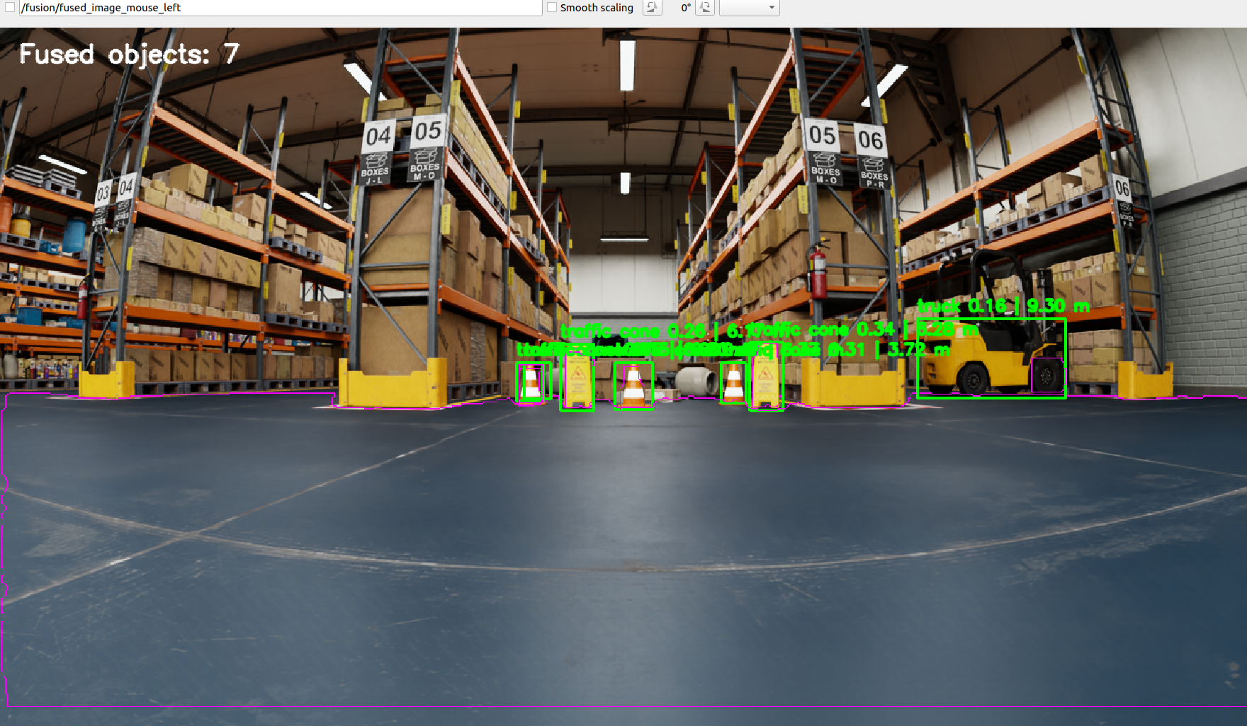
The strongest range-dependent effect was the reduction in available LiDAR support as objects became farther away. The viewpoint changes also altered the number and distribution of projected returns because object surfaces, occlusions, and image occupancy changed. These effects are expected in real multi-modal perception and are important when setting minimum-support thresholds for object-level depth estimation.
5. Extrinsic Calibration Sensitivity
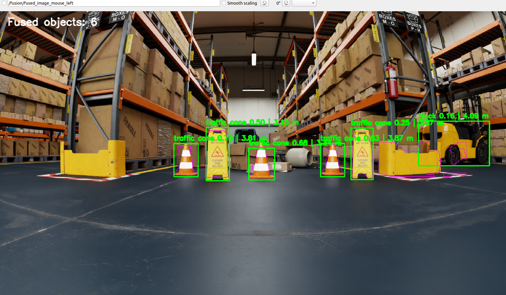
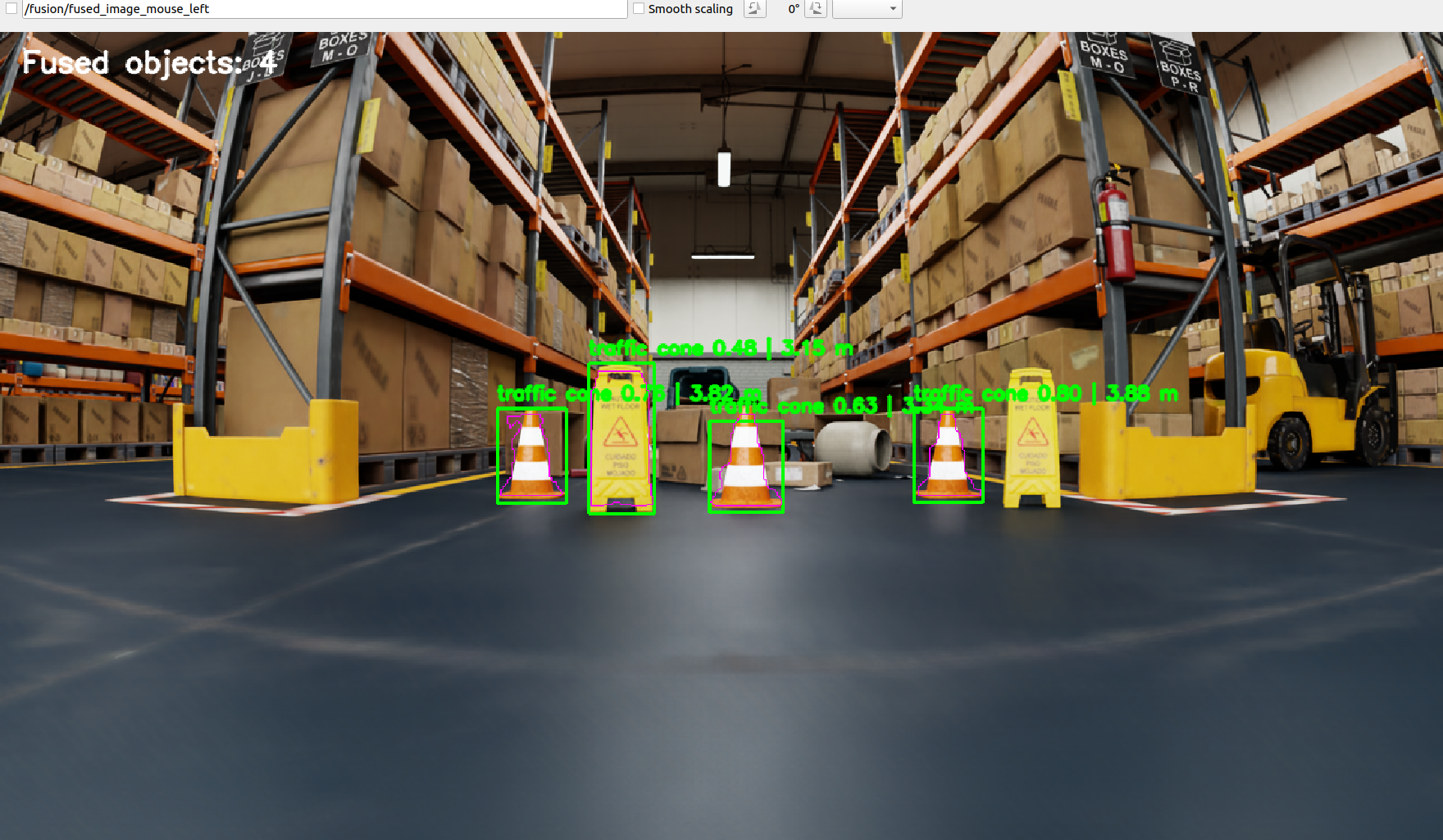
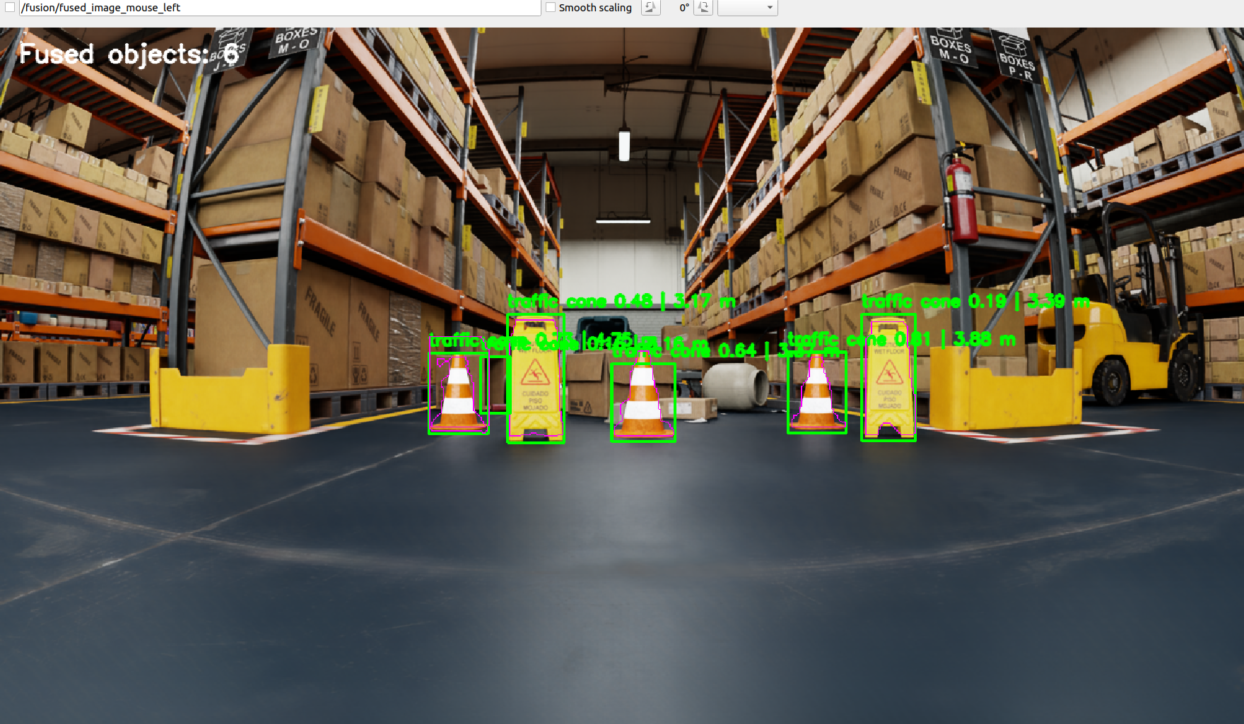
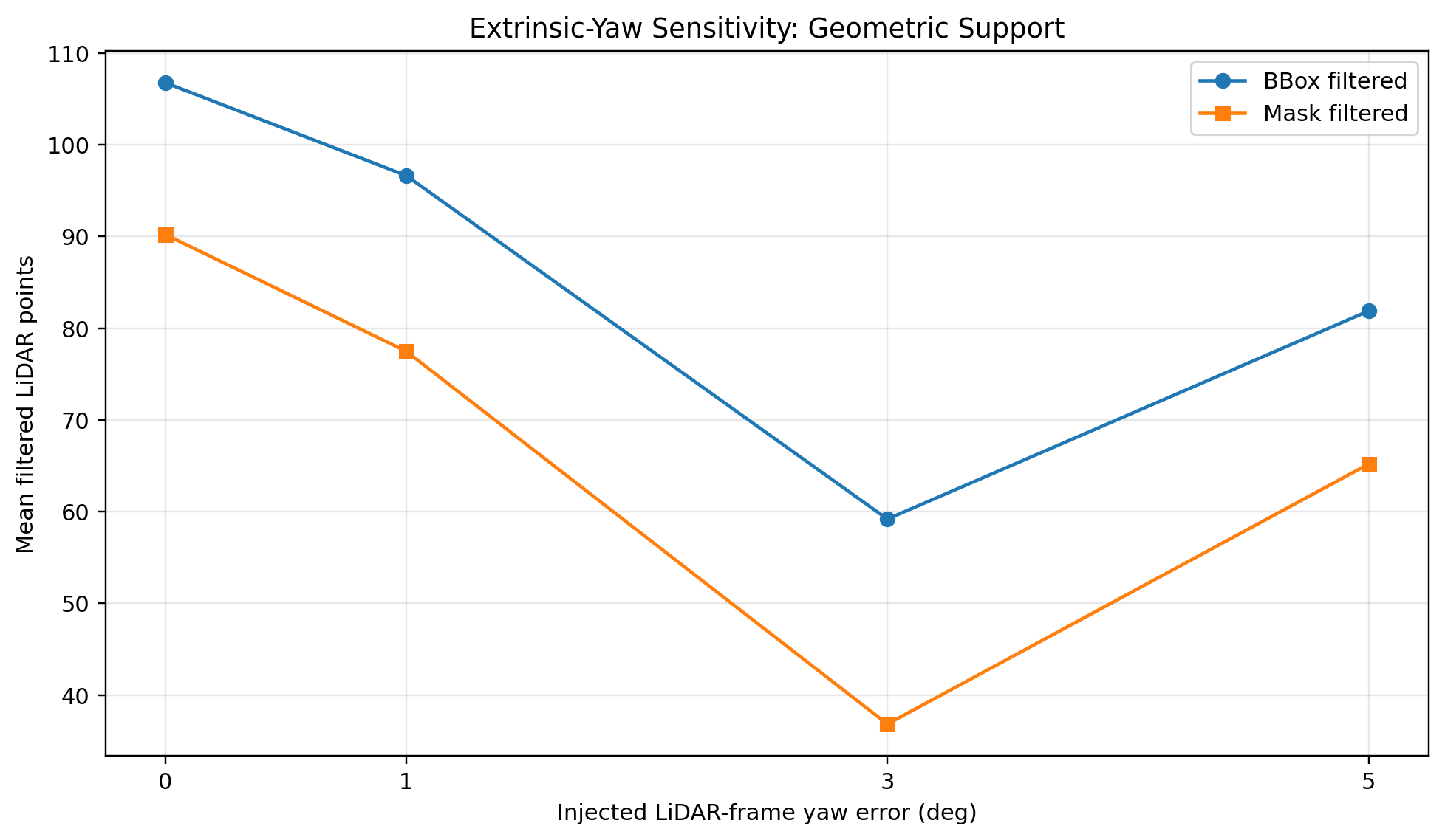
A second controlled experiment evaluates how geometric association degrades when LiDAR-to-camera yaw calibration is deliberately perturbed. The nominal extrinsic transform is used as the 0° reference, after which +1°, +3°, and +5° yaw errors are injected into the LiDAR-frame rotation before the nominal camera transform is applied. All other processing parameters remain unchanged.
This is not intended to emulate every possible calibration error. Translation error, roll/pitch error, timing offset, or a full six-degree-of-freedom perturbation could also be evaluated. Yaw was selected because it produces an intuitive horizontal projection shift in this warehouse scene and allows the geometric sensitivity of the association stage to be isolated with a single controlled variable.
6. BBox vs. Mask Association
Two object-association strategies were evaluated. The bounding-box method keeps projected LiDAR points that fall anywhere inside the detector box, while the mask method keeps only points whose image coordinates fall inside the FastSAM object mask. Mask association can reduce background contamination when the mask accurately follows the object boundary, but it is not automatically superior: a poor mask can include irrelevant surfaces or exclude valid LiDAR returns.
The experiments therefore treat BBox and mask association as complementary strategies rather than assuming one universally dominates the other. Compact, well-separated objects can benefit from mask refinement, while larger or visually ambiguous structures may be more stable with BBox association followed by depth clustering.
7. Failure Analysis
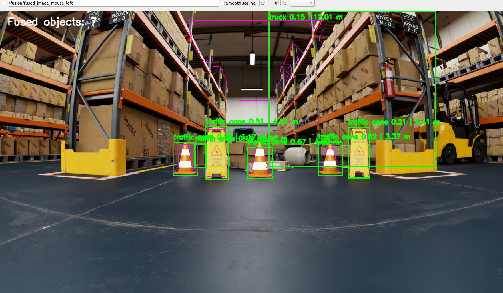
The open-vocabulary detector occasionally assigned the label truck to
warehouse shelving. Those samples were excluded from the quantitative fusion conclusions
because the semantic class itself was incorrect. This is an important systems-level result:
even when the geometric projection stage is functioning correctly, an upstream perception
error can propagate through association and produce a plausible but semantically incorrect
3D estimate.
A second failure mode occurs when the segmentation mask spreads into a neighboring or background region. In that case the mask may admit LiDAR points from the wrong physical surface. The depth-clustering stage reduces this risk, but calibration error or severe mask spill can still generate a geometrically supported yet incorrect depth cluster.
8. Experimental Takeaways
The final pipeline maintained geometric fusion under controlled viewpoint changes and continued producing object-level range estimates at the increased sensing distance, although LiDAR support decreased substantially with range. The extrinsic perturbation experiment demonstrated that even small calibration errors can reduce geometrically consistent support, and larger errors can lead to incorrect surface reassociation rather than simply reducing the number of points.
The project therefore goes beyond a visual overlay demonstration: it evaluates how association quality changes under controlled pose, range, and calibration perturbations, and it documents both successful operating conditions and observed failure modes.
9. Technical Report
Technical Report
The full report contains the coordinate-transform derivation, algorithm-selection rationale, controlled experimental methodology, quantitative interpretation, limitations, and detailed failure analysis.
Download Report — Coming Soon
Project by Sooyong Kim · ROS 2 Robotics Portfolio